Belt Conveyor
Conveying Equipment
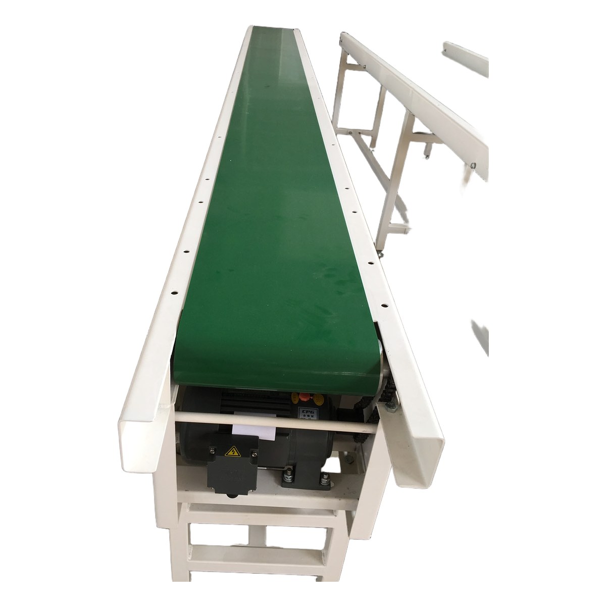
Belt Conveyor
1. Product Overview
The belt conveyor is a continuous material handling system that uses a flexible, endless belt as both the material-carrying medium and the traction element. It is one of the most versatile and widely deployed conveying devices in modern industrial production, extensively applied across metallurgy, mining, coal, electric power, building materials, chemical processing, grain handling, ports, and logistics. Its fundamental advantages include simple structure, smooth and reliable operation, large conveying capacity, low operating cost, strong adaptability to diverse materials, and ease of automation and integration into complex process flows.
Belt conveyors can transport a broad spectrum of bulk and packaged materials, ranging from fine powders and granules to large lump materials and finished components. The conveyor belt moves along a path defined by a series of idlers and pulleys, forming a continuous loop. The upper strand (carrying side) supports and transports the loaded material, while the lower strand (return side) carries the empty belt back to the loading point. By configuring the idler arrangement and belt type, belt conveyors can handle horizontal runs, inclined sections, and even vertical lifting in specialized designs such as corrugated sidewall and pipe conveyors.
The modular nature of belt conveyor systems allows for virtually unlimited layout flexibility. Straight sections can be combined with inclined segments, concave and convex curves, and transfer points to accommodate virtually any plant topology. With belt widths ranging from 500 mm to 1600 mm and beyond, conveying capacities from 50 to over 5000 tonnes per hour, and single-flight lengths exceeding 2000 metres, belt conveyors are equally suited to short in-plant transfers and long-distance overland hauling. The system can be further enhanced with features such as trippers, stackers, ploughs, weigh scales, and metal detectors to meet specific operational requirements.
2. Working Principle
The belt conveyor operates on the principle of friction-driven traction. An electric motor drives the drive pulley (head pulley) through a reducer and coupling. The frictional force between the drive pulley surface and the conveyor belt causes the belt to move. Because the material rests on the belt and moves together with it, there is no relative sliding between the material and the belt surface, which results in low running resistance, low energy consumption, and gentle material handling. The belt forms a closed loop around the head pulley, tail pulley, and any intermediate bend pulleys, with the carrying strand supported by troughing idlers and the return strand supported by flat return idlers.
Material is loaded onto the belt at the tail end (or at any intermediate loading point) through a feeding chute or hopper. As the belt advances, the material is carried forward and discharged at the head end either by gravity over the head pulley or by a plough or tripper at an intermediate point. The tensioning device, located at the tail end or at an appropriate location, maintains the required belt tension to prevent slippage between the belt and the drive pulley and to limit belt sag between idlers. Proper tensioning is essential for reliable operation and for ensuring that the belt tracks correctly along the conveyor centreline.
The amount of frictional force available at the drive pulley depends on the belt tension, the wrap angle around the pulley, and the coefficient of friction between the belt and the pulley surface. When a single drive pulley cannot provide sufficient tractive effort, dual pulley drives or intermediate drives along the conveyor length may be employed. For steep incline or vertical conveying applications, corrugated sidewall belts with cross-cleats or pipe conveyor designs are used to prevent material from sliding back or spilling. The overall conveying efficiency and power consumption are influenced by factors including belt speed, material load, incline angle, idler spacing, and belt tension.
3. System Classification
3.1 Classification by Belt Type
Flat Belt Conveyor: Utilizes a flat conveyor belt carried on flat idlers or a flat slider bed. It is the simplest and most economical type, ideally suited for horizontal or low-incline conveying (up to approximately 18 degrees) of packaged goods, unit loads, and bulk materials where spillage is not a concern. Flat belt conveyors are widely used in assembly lines, inspection stations, sorting systems, and light-duty bulk handling. Their straightforward design makes them easy to install, operate, and maintain.
Troughed Belt Conveyor: The carrying-side idlers are arranged in a trough shape (typically 20-degree, 35-degree, or 45-degree troughing angle) to form the belt into a trough cross-section that increases the material cross-sectional area and prevents spillage. Troughed belt conveyors are the most common type for bulk material handling, offering significantly higher capacities than flat belts at the same speed and width. They are used extensively in mining, power plants, and bulk terminals for transporting coal, ore, aggregate, grain, and other loose bulk materials over long distances and moderate inclines.
Corrugated Sidewall Belt Conveyor: Features corrugated rubber sidewalls and cross-cleats bonded to the belt, enabling steep-angle and vertical conveying (from 30 degrees up to 90 degrees). This type dramatically reduces the conveyor footprint compared to conventional troughed conveyors and eliminates the need for transfer points on inclined runs. Corrugated sidewall conveyors are ideal for ship loading and unloading, stockyard stacking, and any application where space is limited and high lift is required.
3.2 Classification by Application
General-Purpose Belt Conveyor: Designed for standard industrial bulk material handling under normal ambient conditions. It uses ordinary rubber belt, carbon steel frame, and standard-duty idlers. This is the most widely applied category, covering the majority of conveying tasks in mining, metallurgy, building materials, and other industries. The design follows established standards such as GB/T 10595 and DIN 22101, ensuring interchangeability and reliability.
Mobile Belt Conveyor: Mounted on wheels, crawler tracks, or rail-mounted chassis, mobile belt conveyors can be relocated easily to accommodate changing operational layouts. They are commonly used in construction sites, stockyards, ports, and warehouses where temporary or semi-permanent conveying is needed. Mobile units may be self-propelled or towable and often feature adjustable height and inclination for versatile material handling.
Fixed Belt Conveyor: Permanently installed on a concrete or steel foundation, fixed belt conveyors are designed for long-term, high-capacity operation in mines, power plants, steel mills, and processing facilities. They are engineered for maximum reliability, minimal downtime, and low maintenance over a service life of 20 years or more. Fixed conveyors may extend over several kilometres in large mining and port operations.
Heat-Resistant Belt Conveyor: Engineered for conveying hot materials such as sintered ore, clinker, slag, and hot coke at temperatures up to 200 degrees Celsius or higher. It uses special heat-resistant rubber or silicone belts, heat-resistant idler bearings, and protective shields to withstand thermal stress. The frame and components are designed to accommodate thermal expansion and to protect personnel from burn hazards.
Cold-Resistant Belt Conveyor: Designed for operation in arctic and sub-zero environments down to minus 40 degrees Celsius. It employs cold-resistant belt compounds that remain flexible at low temperatures, special low-temperature lubricants for bearings, and insulated or heated drive units. Cold-resistant conveyors are essential in open-pit mines, ports, and processing plants located in northern latitudes and high-altitude regions.
Corrosion-Resistant Belt Conveyor: Constructed with corrosion-resistant materials such as stainless steel frames, galvanized components, and chemically resistant belt covers for service in aggressive chemical, marine, or acidic environments. This type is commonly used in chemical plants, fertilizer factories, coastal installations, and wastewater treatment facilities where exposure to corrosive substances would rapidly degrade standard equipment.
3.3 Classification by Drive Method
Single Pulley Drive: A single drive pulley, typically at the head end, provides all the tractive effort. This is the simplest and most common drive arrangement, suitable for short to medium-length conveyors with moderate power requirements. The drive unit consists of a motor, reducer, coupling, and brake mounted on a common base plate. For long conveyors, the wrap angle may be increased by a snub pulley to improve traction.
Dual Pulley Drive: Two drive pulleys, usually arranged in tandem at the head end, share the driving load. This arrangement doubles the available frictional contact and allows higher belt tensions to be transmitted without slippage, making it suitable for long-distance, high-capacity conveyors. The two drives may operate at the same or different speeds, with coordinated control to ensure balanced load sharing between the two pulleys.
Center (Intermediate) Drive: The drive unit is located at an intermediate point along the conveyor rather than at the head or tail. Center drives are used on very long conveyors where a single head drive would require an impractically large motor, or where space constraints at the ends preclude drive installation. Multiple intermediate drives can be spaced along the conveyor to distribute the pulling force evenly, reducing belt tension and allowing lighter belt construction.
4. Detailed Technical Parameters
4.1 Basic Parameters
| Parameter | Value | Remarks |
|---|---|---|
| Belt width | 500 / 650 / 800 / 1000 / 1200 / 1400 / 1600 mm | Selected per conveying capacity |
| Belt speed | 0.8 - 5.0 m/s | Determined by material characteristics |
| Conveying capacity | 50 - 5000 t/h | Depends on belt width, speed, and material |
| Conveying length | Up to 2000 m (single flight) | Longer distances use multi-point drives |
| Incline angle | Horizontal to 30° (flat) / 30° to 90° (troughed/sidewall) | Determined by material properties |
| Motor power | 1.5 - 500 kW | Depends on capacity, length, and incline |
| Idler spacing | 1000 - 1500 mm (carrying side) | Determined by load and belt width |
| Idler diameter | 89 / 108 / 133 / 159 mm | Selected per belt width and load |
4.2 Flat Belt Conveyor Parameters
| Parameter | B500 | B650 | B800 | B1000 | B1200 |
|---|---|---|---|---|---|
| Conveying capacity (t/h) | 50-100 | 80-200 | 150-350 | 250-600 | 400-1000 |
| Belt speed (m/s) | 1.0-2.0 | 1.0-2.5 | 1.25-3.15 | 1.6-4.0 | 2.0-5.0 |
| Max. incline angle (°) | 18 | 18 | 18 | 18 | 18 |
| Idler diameter (mm) | 89 | 108 | 108 | 133 | 133 |
| Motor power (kW) | 1.5-15 | 2.2-22 | 3-37 | 5.5-55 | 11-90 |
| Max. conveying length (m) | 300 | 500 | 800 | 1200 | 1500 |
4.3 Conveyor Belt Specifications
| Belt Type | Fabric Plies | Top Cover (mm) | Belt Thickness (mm) | Tensile Strength (N/mm) | Application |
|---|---|---|---|---|---|
| CC-56 | 3 | 1.5 | 6 | 56 | Light-duty bulk materials |
| NN-100 | 3 | 3.0 | 8 | 100 | Medium-duty bulk materials |
| NN-200 | 4 | 4.5 | 10 | 200 | Heavy-duty bulk materials |
| EP-200 | 4 | 4.5 | 10 | 200 | Heavy-duty bulk materials |
| EP-300 | 5 | 6.0 | 12 | 300 | Large-capacity / hard rock |
| ST-1000 | 0 (steel cord) | — | 12 | 1000 | Long-distance / high-power |
4.4 Overall Dimensions
| Belt Width (mm) | Frame Width (mm) | Frame Height (mm) | Feed Hopper (mm) | Guide Rail Height (mm) | Equipment Weight (kg/m) |
|---|---|---|---|---|---|
| 500 | 850 | 700 | 500x500 | 300 | 35-50 |
| 650 | 1050 | 850 | 650x600 | 350 | 45-70 |
| 800 | 1250 | 950 | 800x700 | 400 | 60-95 |
| 1000 | 1500 | 1100 | 1000x800 | 450 | 80-130 |
| 1200 | 1750 | 1250 | 1200x900 | 500 | 110-175 |
5. Core Component Selection
5.1 Running Belt
The conveyor belt is the single most critical component of the belt conveyor, serving simultaneously as the load-carrying medium and the traction member. Belt selection depends on the material characteristics, operating conditions, and conveyor geometry. According to the carcass type, belts are classified into cotton canvas (CC), nylon (NN), polyester (EP), and steel cord (ST) constructions. The CC-type belt offers good flexibility and troughability but relatively low tensile strength, making it suitable for short, light-duty conveyors. NN-type belts feature high elongation and excellent impact resistance, while EP-type belts have lower elongation and better dimensional stability under load. ST-type (steel cord) belts provide the highest tensile strength and lowest elongation, essential for long-distance, high-tension applications.
The top cover compound is selected based on the material being handled: general-purpose rubber for ordinary bulk materials, heat-resistant rubber (grade T1/T2/T3) for hot materials, cold-resistant rubber for sub-zero conditions, oil-resistant rubber for oily materials, and food-grade rubber (white or translucent) for food and pharmaceutical products. Belt joint methods include mechanical splicing (for light-duty and temporary installations), cold vulcanization, and hot vulcanization (the preferred method for permanent, high-strength joints). The joint efficiency of a properly executed hot vulcanized splice can reach 90 to 100 percent of the belt's rated tensile strength.
5.2 Rollers
Rollers (idlers) are the rotating components that support the belt and the material load along the conveyor. They are classified into carrying idlers (upper strand), return idlers (lower strand), and impact idlers (at loading points). Carrying idlers may be flat (single roll) or troughed (typically three-roll sets arranged at 20, 35, or 45 degrees). The roller shell is typically made of seamless steel tube (STKM or equivalent), with precision bearings (commonly 6204, 6205, 6206, or 6308 series) sealed with labyrinth or contact seals to exclude dust and moisture. High-quality rollers have a rotational resistance of less than 1 Newton-metre and are designed for a service life exceeding 30,000 hours under rated load.
Impact idlers, installed at loading and transfer points, use rubber discs or rings on the steel roller to absorb the kinetic energy of falling material and protect the belt from damage. Self-aligning (training) idlers are installed at intervals to detect and correct belt misalignment, preventing the belt from running off the idlers and contacting the frame. Return idlers are typically flat single-roll units, although v-return or garland return idlers may be used on wide, high-tension belts. Disc return idlers, with spaced rubber discs, are used to clean the belt and prevent material build-up on the return strand.
5.3 Drive Unit
The drive unit provides the motive power to move the belt and consists of an electric motor, reducer (gearbox), coupling, brake or backstop, and drive pulley. For standard applications, Y-series three-phase asynchronous motors are used with hard-surface helical or bevel-helical gear reducers. The motor and reducer are connected via an elastic or gear coupling that accommodates misalignment and dampens torsional vibrations. Fluid couplings may be installed between the motor and reducer to provide smooth, controlled starting and to protect the drive train from overload.
The drive pulley is typically lagged with a rubber or ceramic layer to increase the coefficient of friction between the pulley and the belt, preventing slippage under high-tension conditions. Ceramic lagging, with raised ceramic tiles embedded in a rubber matrix, provides the highest friction coefficient and is recommended for high-power, high-tension drives. Backstops (one-way clutches) are installed on the drive shaft to prevent reverse motion on inclined conveyors in the event of a power failure or emergency stop. Electromagnetic or electro-hydraulic brakes provide controlled stopping and holding functionality.
5.4 Tension Device
The tension device maintains the required minimum belt tension to prevent slippage at the drive pulley and to limit belt sag between idlers to an acceptable level (typically less than 2 percent of the idler spacing). Screw-type tension devices use threaded rods to manually adjust the position of the tail pulley; they are simple, compact, and economical, suitable for short conveyors under 50 metres where belt elongation is minimal and can be compensated manually during periodic maintenance.
Counterweight (gravity) tension devices use a weighted carriage to automatically maintain constant belt tension. They are self-compensating for belt elongation and require no external power, making them reliable and maintenance-free. Counterweight take-ups are the standard choice for medium to long conveyors (50 to 500 metres). Pneumatic or hydraulic tension devices use pressurized cylinders to apply and control belt tension with high precision. They offer fast response to tension fluctuations and can be integrated into automatic tension control systems, making them ideal for large, high-speed conveyors and for installations where space is limited.
5.5 Frame and Idlers
The conveyor frame is the structural backbone that supports all rotating components, the belt, and the material load. It is typically fabricated from rolled steel sections (H-beams, channels, or angle iron) welded or bolted into rigid frames. The frame design must account for static loads (equipment weight, material weight), dynamic loads (starting and stopping forces, impact at loading points), and environmental loads (wind, snow, seismic). For ground-mounted conveyors, the frame rests on concrete foundations or steel support trestles. For overhead conveyors, the frame may be suspended from roof structures or supported on gantry towers.
Idler frames (brackets) are bolted or welded to the main conveyor frame and hold the idler rolls at the correct angle and alignment. Standard troughing idler frames are designed to hold three rolls at 20, 35, or 45 degrees. Transition idlers are installed at the head and tail ends where the belt transitions from flat to troughed profile. The spacing of carrying idlers typically ranges from 1000 to 1500 mm depending on belt width, material density, and load; idler spacing at loading points is reduced to 300 to 600 mm to provide additional belt support. Return idler spacing is generally 2500 to 3000 mm. All frame components are treated with anti-corrosion paint or hot-dip galvanizing for outdoor installations.
6. Typical Application Fields
Mining and Metallurgy: Belt conveyors are the primary material handling equipment in open-pit and underground mines, transporting raw ore, overburden, coal, and processed minerals from the extraction face to processing plants, stockpiles, or rail/ship loading facilities. In metallurgical plants, they handle raw materials such as iron ore, coke, limestone, and sinter, as well as finished products like pellets and slabs. The mining sector demands conveyors that are rugged, reliable, and capable of handling highly abrasive, heavy materials in harsh environments with extreme dust, moisture, and temperature variations.
Electric Power: In thermal power plants, belt conveyors form the backbone of the coal handling system, transporting coal from the receiving area (railcar dump, ship unloader, or truck dump) through crushing and screening stations to the boiler bunkers. They are also used for limestone handling in flue gas desulfurization systems and for bottom ash and fly ash conveying. Power plant conveyors must operate continuously with extremely high availability (above 99 percent) and require robust dust suppression and environmental protection measures.
Building Materials: Cement plants, aggregate quarries, and brickworks rely heavily on belt conveyors to transport raw materials such as limestone, clay, shale, sand, and gypsum, as well as intermediate and finished products including clinker, cement, and aggregates. The highly abrasive nature of many building materials demands wear-resistant belts, heavy-duty idlers, and frequent maintenance of wear components. High-temperature applications (clinker conveying) require heat-resistant belts and specialized idler bearings.
Chemical Industry: Belt conveyors in chemical plants transport raw materials such as fertilizer granules, soda ash, salt, sulfur, and various chemical powders and granules. Many chemical materials are corrosive, hygroscopic, or toxic, requiring corrosion-resistant construction (stainless steel or FRP frames), sealed or enclosed belt designs, and specialized belt cover compounds (oil-resistant, acid-resistant, or food-grade). Dust-tight enclosures and gas-tight connections are essential for handling hazardous or environmentally sensitive materials.
Grain and Food: The grain industry uses belt conveyors extensively in silo complexes, feed mills, flour mills, and grain terminals for handling wheat, corn, barley, soybeans, rice, and other grains. Food-grade conveyors must comply with strict hygiene and food safety regulations, using white food-grade belt covers, stainless steel components, easy-clean designs with no dead corners, and enclosed structures to prevent contamination. Gentle handling is critical to minimize grain damage and breakage.
Ports and Logistics: In seaports and river ports, belt conveyors are the core equipment of dry bulk terminals, moving coal, iron ore, grain, fertilizer, and other commodities between ship, stockyard, and land transport (rail or truck). Overland conveyors may extend several kilometres from mine to port, replacing truck fleets with a continuous, low-cost, environmentally friendly transport solution. In logistics centres and warehouses, belt conveyors are integral to parcel sorting, package handling, and distribution systems, where they are combined with barcode readers, weight checkers, and diverter mechanisms for automated sorting.
7. Design Standards and Certifications
7.1 National Standards (China)
GB/T 10595 - Belt Conveyors - Technical Specifications: This is the fundamental national standard for belt conveyor design, manufacturing, inspection, and acceptance in China. It covers dimensional tolerances, performance requirements, safety provisions, and test methods for all types of belt conveyors. Compliance with GB/T 10595 ensures that the equipment meets the minimum quality and safety requirements for the Chinese market.
GB/T 7984 - Conveyor Belts of Textile Construction for General Use: Specifies the technical requirements, test methods, and acceptance criteria for textile-carcass conveyor belts used in general-purpose applications, including tensile strength, elongation, abrasion resistance, and adhesion properties of the belt plies and covers.
7.2 Industry Standards
JB/T 7854 - Idlers for Belt Conveyors: Defines the technical requirements, dimensional parameters, and inspection methods for carrying idlers, return idlers, impact idlers, and self-aligning idlers. It covers roller diameter, bearing selection, rotational resistance, seal performance, and service life requirements.
7.3 International Standards
ISO 9001 - Quality Management System Certification: Ensures that the manufacturer maintains a comprehensive quality management system covering design, procurement, production, inspection, and service processes, providing confidence in product consistency and continuous improvement.
CE Certification - European Conformity: Mandatory for products sold in the European Economic Area. CE marking indicates that the equipment complies with the applicable EU directives, including the Machinery Directive (2006/42/EC), the Low Voltage Directive, and the ATEX Directive for equipment used in explosive atmospheres.
DIN 22101 - Continuous Conveyors - Belt Conveyors for Loose Bulk Materials - Basis for Calculation and Dimensioning: The German standard that provides the most comprehensive and widely referenced methodology for belt conveyor design, covering belt tension calculation, drive power, idler spacing, belt safety factors, and structural design. DIN 22101 is considered the gold standard for long-distance, high-capacity conveyor engineering worldwide.
CEMA - Conveyor Equipment Manufacturers Association Standard: The North American standard for belt conveyor design, published by CEMA (USA). It provides calculation methods, design guidelines, and component specifications widely used throughout the Americas and in many international projects. CEMA Class ratings (CEMA C, D, E, etc.) define idler load capacity and bearing life standards.
7.4 Special Certifications
Explosion-proof certification (Ex) for applications handling combustible or explosive materials. Food-safety certification for applications in food processing.
8. Customizable Options
| Configuration Item | Available Options | Application Scenario |
|---|---|---|
| Belt type | Flat / Troughed / Corrugated sidewall | Selected per incline angle and material |
| Belt material | General rubber / Heat-resistant / Cold-resistant / Oil-resistant / Food-grade | Selected per material characteristics and environment |
| Idler type | Flat / Troughed (20°/35°/45°) / Impact / Self-aligning / Disc return | Selected per load, belt width, and duty |
| Drive mode | Single pulley / Dual pulley / Center (intermediate) drive | Selected per power and distance requirements |
| Tension type | Screw / Counterweight (gravity) / Pneumatic / Hydraulic | Selected per conveyor length and belt type |
| Brake | Electromagnetic / Electro-hydraulic / Backstop (one-way clutch) | Selected per incline and safety requirements |
| Cleaning device | Scraper blade / Air blower / Rotary brush / Vibrating cleaner | For sticky or wet material cleaning |
| Safety protection | Belt sway switch / Speed monitor / Pull-cord emergency stop / Slip detector | Safety and automation control |
| Sealing | Open / Semi-enclosed / Fully enclosed (dust-tight) | Per dust control and environmental requirements |
| Mobility | Fixed / Mobile (wheeled) / Relocatable (skid-mounted) | Per operational flexibility requirements |
9. Warranty Terms
9.1 Warranty Period
Complete Machine Warranty: The warranty period for the complete belt conveyor system is twelve (12) months from the date of final acceptance and commissioning at the customer's site. During this period, the supplier shall, at its own expense, repair or replace any component that fails due to defects in design, materials, or workmanship. The warranty covers all mechanical, electrical, and structural components forming part of the delivered system.
Structural Components Warranty: Main structural components including the conveyor frame, drive pulley, tail pulley, bend pulleys, and idler frames are warranted for twenty-four (24) months from the date of acceptance. This extended warranty reflects the long service life and critical nature of structural elements that are not subject to normal wear.
Consumable Parts Warranty: Consumable and wear parts including the conveyor belt, idler bearings, scraper blades, and lagging are warranted for six (6) months from the date of initial operation. These components are subject to normal wear and their service life depends on operating conditions, material abrasiveness, and maintenance practices.
9.2 Warranty Scope
The warranty covers all failures and defects attributable to the manufacturer, including but not limited to: design errors resulting in inadequate strength or performance; material defects such as inclusions, cracks, or substandard mechanical properties; manufacturing defects such as incorrect machining dimensions, poor weld quality, or improper assembly; and corrosion or degradation of components due to inadequate surface treatment under specified operating conditions.
The warranty does not cover: damage caused by improper operation, misuse, or use beyond the specified design parameters; damage resulting from inadequate maintenance, failure to follow the recommended maintenance schedule, or use of non-approved replacement parts; normal wear and tear of consumable items; modifications, alterations, or repairs performed by unauthorized personnel; and damage caused by force majeure events including fire, flood, earthquake, lightning, and acts of war.
9.3 After-Sales Service
The supplier provides lifetime technical support including telephone consultation, remote diagnosis, and on-site service. Upon receiving a fault notification from the customer, the supplier shall respond within twenty-four (24) hours and dispatch a service engineer to the site within forty-eight (48) hours for domestic customers, or within seventy-two (72) hours for overseas customers. Post-warranty technical services and spare parts supply are available on a paid basis, with preferential pricing for original equipment parts and guaranteed availability of critical spare parts for a minimum of ten (10) years after delivery.
10. Packaging and Delivery
10.1 Packaging Method
The complete belt conveyor system is disassembled into major sub-assemblies for packaging and shipment: drive unit (motor, reducer, coupling, brake, and drive pulley pre-assembled on a common base plate), tail section with tension device, intermediate frame sections (standard lengths of 3 to 6 metres), carrying idlers, return idlers, bend pulleys, conveyor belt (rolled on a mandrel), and accessories (skirts, chutes, covers, safety devices). Each sub-assembly is packed in a wooden crate or steel frame suitable for overland and sea transport, with internal cushioning materials (foam, rubber, corrugated board) to prevent damage from vibration and impact during transit.
Precision components such as the motor, reducer, instruments, and electrical control panels are sealed in moisture-proof bags with desiccant and packed in reinforced wooden cases. The conveyor belt is wrapped with protective fabric and stored on a specially designed reel to prevent deformation. All packages are clearly marked with the project name, item number, weight, dimensions, and handling instructions. An itemized packing list is attached to each package, and a master packing list is provided for the entire shipment.
10.2 Delivery Period
Standard models: Forty-five (45) to sixty (60) working days from the effective date of the contract and receipt of the down payment. Non-standard or custom-engineered products: Delivery period is subject to separate negotiation based on the complexity of the design and manufacturing requirements, typically sixty (60) to ninety (90) working days. Delivery documentation includes: product certificate of conformity, factory test report, operation and maintenance manual (in English or as agreed), spare parts list, and as-built drawings.
10.3 Transportation Requirements
During transportation, all packages shall be handled with care to prevent severe vibration, impact, and exposure to moisture. Extra-long components (frame sections, belt reels) shall be transported on suitable flatbed trailers with proper securing and oversized load markings. Equipment shall not be stored outdoors uncovered; if temporary outdoor storage is unavoidable, waterproof tarpaulins shall be used and components shall be elevated off the ground on dunnage to allow air circulation and prevent moisture damage. The customer shall inspect all packages upon receipt and report any damage or shortage within seven (7) days.
11. Information Required for Inquiry
To ensure accurate equipment selection, optimal design, and competitive quotation, please provide the following information when submitting an inquiry:
| No. | Information Item | Description |
|---|---|---|
| 1 | Material name and characteristics | Name, bulk density (t/m³), particle size (mm), moisture content, temperature (°C), abrasiveness, corrosiveness, and any other special properties |
| 2 | Required conveying capacity | Maximum and average capacity (t/h or m³/h), including any anticipated future capacity increases |
| 3 | Conveying distance and incline | Horizontal distance (m), vertical lift (m), incline angle (°), and profile description (horizontal, inclined, or combined) |
| 4 | Belt speed requirement | Desired or acceptable belt speed range (m/s), or indicate if standard speed is acceptable |
| 5 | Installation site conditions | Available space (width x height), floor load capacity, indoor or outdoor, ambient temperature range, altitude, and any obstructions |
| 6 | Environmental requirements | Explosion-proof (zone and gas group), dust sealing level, noise limits, corrosion resistance, or food-grade requirements |
| 7 | Power supply conditions | Voltage (V), frequency (Hz), phase, and protection level (IP rating) required for the drive motor and control panel |
| 8 | Other special requirements | Multi-point feeding or discharging, belt weighing, metal detection, tripper or plough, cover or enclosure, colour scheme, and any project-specific standards |