Heat Pipe Exchanger
Heat Exchangers
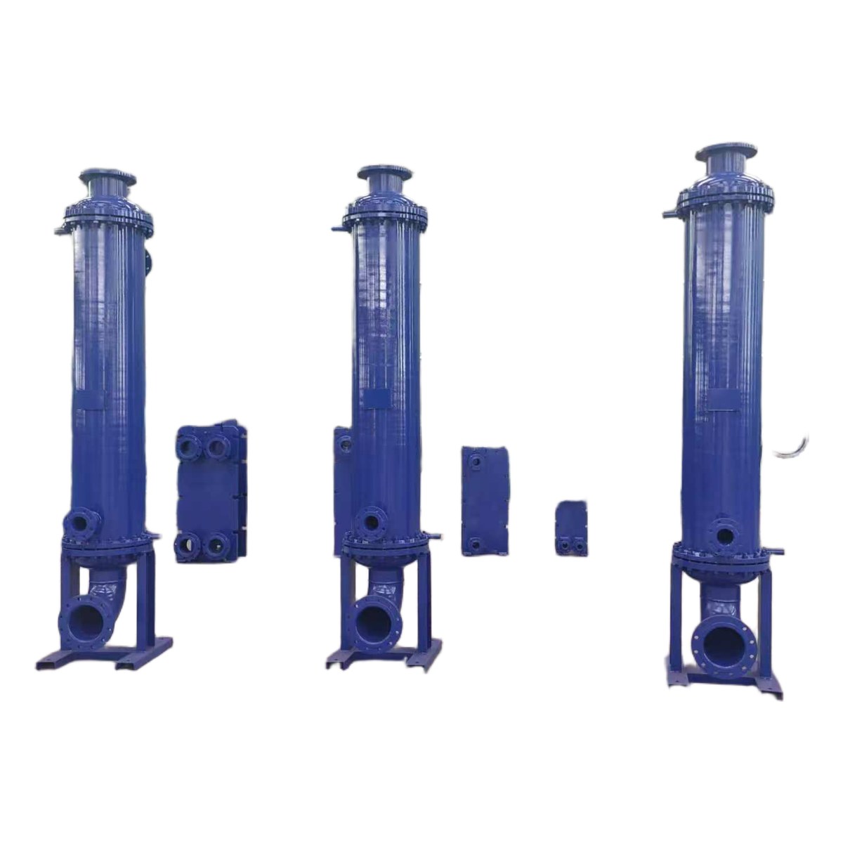
1. Product Overview
The heat pipe heat exchanger is a highly efficient gas-to-gas or gas-to-liquid heat exchange device with heat pipes as its core heat-transfer elements. It consists of a shell, heat pipe bundle, partition plate, inlet/outlet nozzles, and control accessories. Typical applications include boiler waste heat recovery, metallurgical flue gas cooling, chemical gas preheating, and heat recovery in drying systems. Key features: exceptionally high effective thermal conductivity, complete isolation of hot and cold fluids with no cross-contamination, excellent isothermal performance, and easy maintenance thanks to individual tube replacement.
2. Working Principle
The heat pipe is evacuated and charged with a working fluid. The hot end (evaporator section) absorbs heat from the high-temperature fluid, vaporizing the internal working fluid which flows to the cold end (condenser section); at the cold end, it releases latent heat to heat the cold fluid, and the vapor condenses back into liquid, returning to the hot end by capillary force or gravity, cycling continuously. Cold and hot fluids flow outside the pipes on opposite sides of the partition plate, completely isolated.
3. System Classification
By Structural Form:
Integral Heat Pipe Exchanger: Cold and hot chambers integrated, separated by a partition plate, compact structure / Medium-low temperature waste heat recovery
Separate Heat Pipe Exchanger: Evaporator and condenser sections arranged separately, connected by vapor/liquid pipes / Space-constrained or remote heat exchange applications
Fin-tube Heat Pipe Exchanger: Fins added externally to increase heat transfer area / Gas heat exchange, low heat transfer coefficient conditions
4. Detailed Technical Parameters
4.1 Common Materials
| Material | Applicable Media | Remarks |
|---|---|---|
| Carbon Steel Q235B/20G | Flue gas, air (<350℃) | Basic configuration, low cost |
| 304 Stainless Steel | Corrosive flue gas, organic gas | Preferred for corrosion resistance |
| 316L Stainless Steel | Strongly corrosive chemical gas | Special working conditions |
| ND Steel (09CrCuSb) | Sulfur-containing flue gas (resistant to low-temp dew point corrosion) | Recommended for boiler tail-end waste heat recovery |
4.2 Typical Specification Table
| Heat Duty (kW) | Gas Flow Rate (m³/h) | Heat Pipe Dia. | Pipe Arrangement | Heat Transfer Area (m²) |
|---|---|---|---|---|
| 50~500 | 1000~8000 | Φ25~Φ32 | Staggered/In-line | 10~80 |
| 500~2000 | 8000~30000 | Φ32~Φ38 | Staggered | 80~300 |
| 2000~5000 | 30000~80000 | Φ38~Φ51 | Staggered | 300~1000 |
4.3 Design Conditions & Performance
| Parameter | Specification |
|---|---|
| Design Temperature | Normal temp~450℃ (depends on fluid & material) |
| Design Pressure | Atmospheric or slight positive pressure (usually -5kPa~+20kPa) |
| Heat Exchange Efficiency | 40%~70% (depending on process arrangement) |
| Pressure Drop | Hot/Cold side: 300~800Pa (can be designed <500Pa) |
5. Electrical Parameters
| Region | Voltage | Frequency |
|---|---|---|
| China/Russia/Central Asia | 380V | 50Hz |
| Middle East/Southeast Asia/Africa | 400V / 415V | 50Hz |
| South Korea | 380V | 60Hz |
| Americas (if required) | 440V / 480V | 60Hz |
| Note: Heat pipes consume no power; electrical parameters apply only to soot blowers or instruments. |
6. Core Component Selection
| Component | Brand/Material | Features & Applications |
|---|---|---|
| Heat Pipe | Custom processing | Carbon steel-water/steel-Dowtherm/stainless steel, high radial heat flux |
| Fins | Custom processing | High-frequency welded/rolled/L-type wound fins, enhanced gas-side heat transfer |
| Shell | Custom processing | Carbon steel/stainless steel, internal/external insulation design |
| Soot Blower | National standard | Acoustic/steam soot blowing, prevents ash accumulation |
7. Typical Application Fields
Power Industry: Boiler exhaust waste heat recovery
Metallurgical Industry: Heating furnace, blast furnace gas cooling & recovery
Chemical Industry: Reaction gas preheating and cooling
Building Materials: Kiln tail gas waste heat recovery
8. Design Standards & Certifications
| Standard | Description |
|---|---|
| GB 150-2011 | Pressure Vessels (shell application) |
| HGT 20581-2011 | Steel Tubular Heat Exchangers (base application) |
| ISO 9001:2015 | Quality Management System |
| CE / EAC / GOST-R | Available upon request for international orders |
9. Custom Optional Configurations
| Option | Details |
|---|---|
| Pipe Material & Fluid | Carbon steel-water/copper-water/steel-Dowtherm (for >350℃) |
| Fin Type | High-frequency welded/nickel brazed/L-type wound |
| Soot Blowing System | Acoustic/steam soot blower/rapping dust removal |
| Insulation Structure | Internal/external insulation (rock wool/aluminum silicate wool with color-steel cladding) |
10. Warranty Terms
| Equipment Status | Warranty Period | Warranty Scope |
|---|---|---|
| Brand New | 12 months | Shell structure, heat pipe transfer performance, tubesheet seal |
| Refurbished | 6 months | Shell structure, heat pipe transfer performance, tubesheet seal |
| Idle | 3 months | Main functional components |
11. Packaging & Delivery
| Item | Packaging Method |
|---|---|
| Shell | Steel strap bundled nude or tarpaulin wrapped |
| Heat Pipe Assembly | Wooden crate fixed packaging, anti-deformation |
| Instruments / Soot Blowers | Waterproof sealed packaging in wooden cases |
| Shipped by container or bulk carrier. On-site installation guidance available. |
12. Information Required for Inquiry
12. Information Required for Inquiry Cold/hot fluid name, flow rate, inlet/outlet temperature, allowable pressure drop; fluid corrosiveness and dust content; installation space limits; whether a soot blowing system is needed; equipment status preference (new/refurbished/idle); delivery terms (FOB/CIF/DDP); destination port.