Spiral Wound Shell & Tube Condenser
Heat Exchangers
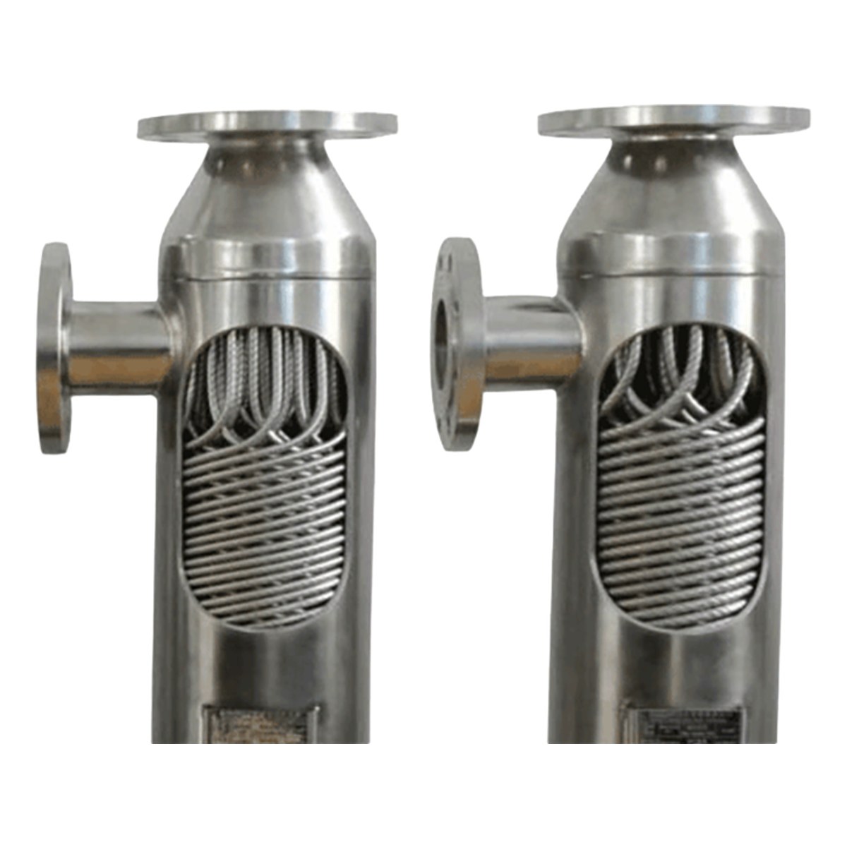
Spiral Wound Shell & Tube Condenser
1. Product Overview
The Spiral Wound Shell & Tube Condenser (also known as a coil-wound heat exchanger or spiral wound tube heat exchanger) is a compact, high-efficiency heat exchange unit in which the heat exchange tubes are wound layer by layer in alternating helix directions onto a center cylinder to form a coil-wound tube bundle, which is then installed inside the shell. It consists of the shell, tubesheet and tube box, the coil-wound bundle (center cylinder plus multiple layers of counter-wound heat exchange tubes), special-shaped spacer bars between layers, a flow guide cylinder and pass partition plates, inlet and outlet nozzles, and supports. The cooling medium (cooling water, chilled brine, low-temperature refrigerant, etc.) flows on the tube side or the shell side while the vapor enters from the other side, condenses on the tube wall surface and releases latent heat to the cooling medium, completing the condensation and cooling process.
Widely used in: overhead condensation and heat recovery in petroleum refining, Rectisol wash in coal chemicals, natural gas liquefaction and BOG recondensation, main heat exchange in air separation and cryogenic units, feed/effluent exchange in ammonia synthesis and hydrogenation units, reflux condensation of reactors in the pharmaceutical and fine chemical industries, solvent recovery and distillation column overhead condensation.
Equipment features: compact structure with a heat transfer area of 100~200 m²/m³ per unit volume; high heat transfer coefficient thanks to the secondary flow induced by spiral flow; high tube side pressure capability with a design pressure up to 35 MPa; the coil-wound bundle can expand and contract freely for self-compensation of thermal expansion, accommodating a wide temperature span of -196℃~400℃; interlayer spacer bars form uniform flow channels with controllable pressure drop; multiple streams can be handled simultaneously; various materials of construction available and custom-built to requirements.
2. Working Principle
The vapor (or hot fluid) enters through the inlet nozzle and is distributed by the pass partition plates into the multiple layers of spiral wound tubes of the coil-wound bundle (or to the shell side), where it exchanges heat with the shell side (or tube side) cooling medium in pure counter-current or cross-flow mode. The tubes are wound at a fixed helix angle with uniform pitch; the fluid follows a spiral path inside the tubes and generates a secondary circulation that thins the boundary layer and raises the heat transfer coefficient. Adjacent wound layers are arranged in opposite directions, which intensifies interlayer disturbance and makes the shell side flow field more uniform. Upon contact with the cooler tube wall surface, the vapor releases its latent heat, condenses into a liquid film and flows downward along the tube wall; the condensate collects and is discharged through the condensate outlet. The special-shaped spacer bars between layers maintain tube spacing and shell side flow channels, allowing non-condensable gas to be discharged through the vent.
3. System Classification
By Structural Type
| Type | Features | Typical Application |
|---|---|---|
| Vertical coil-wound type | Bundle installed vertically, condensate discharged by gravity, small footprint, low installation height | Column overhead condensers, reboilers, small and medium heat exchange units |
| Horizontal coil-wound type | Bundle installed horizontally, easy inspection and bundle withdrawal, flexible layout | Large refining units, natural gas processing, utility heat exchange |
| Multi-stream coil-wound type | Several independent tube bundles arranged in one shell, enabling simultaneous heat exchange of multiple media | Natural gas liquefaction cold boxes, cryogenic separation, multi-stream heat recovery |
| Cold box integrated type | Several coil-wound bundles integrated in one shell and delivered as a complete skid | Air separation units, Rectisol wash, skid-mounted liquefaction plants |
By Heat Transfer Function
| Type | Features | Typical Application |
|---|---|---|
| Condenser | Vapor on tube side or shell side, condensate discharged by gravity or differential pressure | Column overhead condensation, reactor reflux condensation, steam condensation |
| Reboiler | Column bottoms liquid is vaporized and returned to the column, small temperature difference and high heat transfer coefficient | Distillation column bottoms reboiling, evaporator system heating |
| Cooler | Process material cooled to the required process temperature with controllable pressure drop | Process material cooling, product after-cooling |
| Heat recovery unit | Heat recovered between multiple streams, terminal temperature difference down to 1~2℃ | Cryogenic units, cold energy recovery, comprehensive energy utilization |
4. Detailed Technical Parameters
4.1 Common Materials of Construction and Applicable Service Conditions
| Material | Grade | Applicable Media | Remarks |
|---|---|---|---|
| Carbon steel | Q345R/Q245R | Non-corrosive cooling water, non-corrosive process media | Low cost; short service life with corrosive media |
| 304 stainless steel | 06Cr19Ni10 | Weakly corrosive media, general chemical processes | General purpose, good cost-performance |
| 316L stainless steel | 022Cr17Ni12Mo2 | Chloride-containing media, acetic acid, pharmaceutical and coal chemical service | Recommended first choice, excellent corrosion resistance |
| 321 stainless steel | 06Cr18Ni11Ti | High-temperature service, resistance to intergranular corrosion | Suitable for service above 400℃ |
| Duplex stainless steel | S32205/S31803 | Chloride-containing media, seawater cooling, high-stress environments | Excellent resistance to pitting and stress corrosion cracking |
| Titanium (TA2) | Commercially pure titanium | Seawater, wet chlorine, strongly corrosive media | Good thermal conductivity; high cost, supplied on request |
| Hastelloy | C-276 | Strongly corrosive high-temperature media, mixed acid service | Highest cost, custom-built to order |
| Copper alloy | H62/H68/cupronickel | Ammonia-free and chloride-free cooling service | High thermal conductivity; suitable for low temperature difference heat transfer |
4.2 Typical Specifications of Spiral Wound Shell & Tube Condensers
| Coil bundle diameter (mm) | Tube size (mm) | Heat transfer area (m²) | Shell side design pressure (MPa) | Tube side design pressure (MPa) | Design temperature (℃) | Reference condensing capacity |
|---|---|---|---|---|---|---|
| Φ300~500 | Φ12×1.0 | 5~30 | 1.0~4.0 | 5.0~10 | -60~200 | 0.5~3 t/h steam condensation |
| Φ600~1000 | Φ14×1.5 | 30~150 | 1.6~6.4 | 10~25 | -100~300 | 3~15 t/h steam condensation |
| Φ1200~2000 | Φ19×2.0 | 150~600 | 2.5~10 | 16~35 | -196~350 | 15~60 t/h steam condensation |
| Φ2000~3500 | Φ25×2.5 | 600~2000 | 4.0~12 | 20~35 | -196~400 | 60~200 t/h steam condensation |
| Φ3500~4500 | Φ25×2.5/Φ32×3 | 2000~4500 | 6.0~15 | 25~35 | -196~400 | 200~400 t/h steam condensation |
| Custom design | Per process calculation | Per process calculation | ≤20 | ≤40 | -196~450 | Large cold boxes / multi-stream service |
Note: the specifications above are common configurations. The actual design is determined by the process conditions, medium properties, pressure and temperature requirements and allowable pressure drop, and can be customized to requirements. Tube sizes also include Φ16×1.5, Φ19×1.5 and Φ32×2; the reference condensing capacity is based on water vapor condensation.
4.3 Design Conditions and Performance Data
| Parameter | Specification |
|---|---|
| Design pressure range | Shell side: vacuum~12 MPa; tube side: vacuum~35 MPa (higher pressures available on request) |
| Design temperature range | -196℃~400℃ (depending on material of construction and actual service conditions) |
| Overall heat transfer coefficient (typical) | 1000~8000 W/(m²·K) (varies with medium, flow velocity and flow pattern) |
| Heat transfer area per unit volume | 100~200 m²/m³ (Φ12~Φ25 tubes, depending on the number of wound layers) |
| Tubes and winding parameters | Tubes Φ12~Φ25, wall thickness 1.0~2.5 mm; helix angle 3°~20°, arranged at uniform equal pitch within each layer |
| Terminal temperature difference | Pure counter-current arrangement, terminal temperature difference down to 1~2℃ |
| Allowable pressure drop | Controlled to process requirements on both tube side and shell side; can be optimized through pass arrangement and spacer bar selection |
| Winding and NDT | After the coil-wound bundle is formed it is degreased and cleaned as a whole; tube-to-tubesheet weld joints are examined by radiographic or penetrant testing in accordance with NB/T 47013 |
| Design life and applicable standards | Design life ≥20 years; designed and manufactured in accordance with NB/T 10938-2022 and GB/T 151-2014 |
4.4 Electrical Parameters
| Region | Voltage | Frequency |
|---|---|---|
| China / Russia / Central Asia | 380V | 50Hz |
| Middle East / Southeast Asia / Africa | 400V / 415V | 50Hz |
| South Korea | 380V | 60Hz |
| Americas (if required) | 440V / 480V | 60Hz |
Note: standard Spiral Wound Shell & Tube Condensers have no electrical requirements. Electrical parameters apply only when instrumentation, electric heat tracing or remote monitoring is fitted. If such options are involved, please be sure to state the local voltage and frequency when placing the order.
5. Selection of Core Components
| Component | Common Brand / Material | Features and Application |
|---|---|---|
| Heat exchange tubes | Custom (GB/T 14976 stainless steel seamless tubes) | Φ12~Φ25 seamless tubes formed by spiral winding; the core element for pressure containment and heat transfer |
| Center cylinder | Custom (304/316L seamless tube or rolled and welded plate) | Load-carrying mandrel of the coil-wound bundle, also forming the innermost flow channel |
| Special-shaped spacer bar | Custom (stainless steel profile) | Maintains the spacing between adjacent wound layers and forms uniform shell side flow channels |
| Tubesheet and tube box | Custom forging / fabricated plate | Pass division and pressure-tight sealing; material selected according to pressure rating and medium |
| Sealing gaskets | Garlock, Flexitallic, quality domestic brands | Spiral wound metal gaskets and PTFE enveloped gaskets; resistant to high pressure and strong corrosion |
| Instrumentation and safety accessories (optional) | Siemens, E+H, Shanghai Valve Factory, SUFA | Temperature, pressure and level monitoring; safety valves set at 1.05~1.1 times the design pressure |
Customers may specify their preferred brands; for refurbished equipment this is subject to stock availability.
6. Typical Application Fields
Petroleum refining: overhead condensation and low/medium temperature heat recovery in atmospheric and vacuum distillation, catalytic cracking, hydrocracking and reforming units
Coal chemicals: Rectisol wash units, syngas cooling, feed/effluent exchange for methanol synthesis reactors, heat exchange for coal gasification auxiliaries
Natural gas and LNG: main heat exchangers in liquefaction cold boxes, natural gas de-hydrocarbon and dehydration, BOG recondensation
Air separation and cryogenics: main heat exchangers, subcoolers, heat exchange upstream and downstream of expanders, cryogenic heat exchange in Rectisol wash
Pharmaceuticals and fine chemicals: reactor reflux condensation, solvent recovery condensation, distillation column overhead condensation (GMP clean-grade materials available)
New energy and new materials: process condensation of lithium battery electrolyte, polysilicon, biodiesel and oil & fat process heat exchange
7. Design Standards and Certification
| Standard | Description |
|---|---|
| NB/T 10938-2022 | Coil-wound heat exchangers (energy industry standard, dedicated standard for this type of equipment) |
| GB/T 151-2014 | Heat exchangers (basic standard for shell and tube heat exchangers) |
| GB/T 150.1~150.4-2024 | Pressure vessels (general requirements, materials, design, fabrication, inspection and acceptance) |
| TSG 21-2016 | Safety Technical Supervision Regulation for Stationary Pressure Vessels |
| NB/T 47013-2015 | Nondestructive testing of pressure equipment (radiographic, ultrasonic, penetrant, magnetic particle) |
| NB/T 47014-2011 / 47015-2011 | Welding procedure qualification for pressure equipment / welding specification for pressure vessels |
| GB/T 14976-2012 | Seamless stainless steel tubes for fluid transport (heat exchanger tubing) |
| GB/T 27698-2011 | Test methods for the performance of heat exchangers and heat transfer elements |
| JB/T 4711 | Coating and transport packaging of vessels |
| ISO 9001:2015 / CE / EAC / GOST-R | Quality management system; CE (PED 2014/68/EU), EAC and GOST-R can be arranged according to market requirements |
8. Optional Customization
| Option | Details |
|---|---|
| Structural type | Vertical / horizontal / multi-stream / cold box integrated |
| Heat transfer function | Condenser / reboiler / cooler / heat recovery unit |
| Tube size | Φ12×1.0 / Φ14×1.5 / Φ16×1.5 / Φ19×2.0 / Φ25×2.5 / Φ32×3 |
| Tube material | Carbon steel / 304 / 316L / 321 / duplex steel / titanium / Hastelloy / copper alloy |
| Shell and tubesheet material | Carbon steel / stainless steel / duplex steel / titanium clad plate |
| Winding parameters | Helix angle, number of layers, pitch and interlayer spacing optimized to process and pressure drop requirements |
| Nozzle orientation and size | Customized to the site piping orientation; national standard or ANSI flanges available |
| Pass arrangement | Single pass / multi pass; tube side and shell side pass scheme determined by the process |
| Surface treatment | Internal pickling and passivation (stainless steel) or blast cleaning; external anti-corrosion paint / blast cleaning |
| Thermal insulation and cold insulation | Rock wool / aluminum silicate insulation, or perlite and vacuum insulation for cryogenic service; stainless steel or color-coated steel outer cladding |
| Instrumentation | Temperature sensors, pressure gauges, thermowells, level gauges |
| Safety accessories | Safety valve, vent valve, drain valve, overpressure protection |
| Testing requirements | Hydrostatic test and pneumatic tightness test; helium mass spectrometer leak test optional for cryogenic service |
| Seismic design | Seismic calculation and reinforcement (for seismic zones) |
9. Warranty Terms
| Equipment Condition | Warranty Period | Warranty Coverage |
|---|---|---|
| New equipment | 12 months | Shell, coil-wound bundle, heat exchange tubes, tubesheet, tube box, nozzles, gaskets |
| Refurbished equipment | 6 months | Shell, coil-wound bundle, heat exchange tubes, tubesheet, tube box, nozzles, gaskets |
| Idle equipment (as-is supply) | 3 months | Main functional components |
The final warranty terms are governed by the contract. All orders include installation guidance and remote commissioning support.
10. Packaging and Delivery
| Item | Packaging Method |
|---|---|
| Condenser body | Bare packing secured with steel straps or packed in a wooden case; flange faces protected and nozzles fitted with protective caps |
| Spare gaskets | Waterproof sealed and then packed in cartons |
| Small accessories | Packed in cartons or wooden cases |
Estimated container capacity (for reference only, subject to the actual configuration):
Condensers with coil bundle diameter below 1 m: approx. 2-4 units in one 20'GP container
Condensers with coil bundle diameter of 1~1.5 m: approx. 1-2 units in one 20'GP container
Condensers with coil bundle diameter of 1.5~2.5 m: approx. one 40'GP container or one 40'OT container
Condensers with coil bundle diameter of 2.5~3.5 m: one 40'OT container or break bulk shipment
Large cold box integrated units: break bulk shipment or flat rack container
Installation service: on-site installation guidance can be provided. For large projects, technicians can be dispatched to site (travel and accommodation costs borne by the buyer).
11. Information Required for Quotation
To obtain an accurate quotation, please provide the following information:
Process function (column overhead condensation / reflux condensation / reboiling / solvent recovery / cooling / multi-stream heat recovery)
Condensing medium (vapor name, composition, flow rate or condensing duty, in kg/h or kW)
Cooling medium type (cooling water / chilled brine / low-temperature refrigerant / other) and inlet and outlet temperatures
Preferred condensation side: shell side condensation / tube side condensation
Operating pressure and design pressure on the shell side and tube side (positive pressure and vacuum values separately)
Operating temperature and design temperature (please indicate if cryogenic or high-temperature conditions apply)
Required heat transfer area (if known) or process calculation data (duty, temperature difference, allowable pressure drop)
Preferred structural type: vertical / horizontal / multi-stream / cold box integrated
Material requirements for the shell, heat exchange tubes and tubesheet
Coil bundle diameter or installation space limitations
Nozzle orientation and size requirements, flange standard (national standard / ANSI)
Whether thermal insulation or cold insulation is required
Whether instrumentation (temperature, pressure, level) and safety valves are required
Local voltage and frequency (if instrumentation or electric heat tracing is required)
Preferred equipment condition: new / refurbished / idle
Delivery terms: FOB/CIF/DDP; destination port or delivery address (for freight calculation)