RTO Thermal Oxidizer
Environmental Equipment
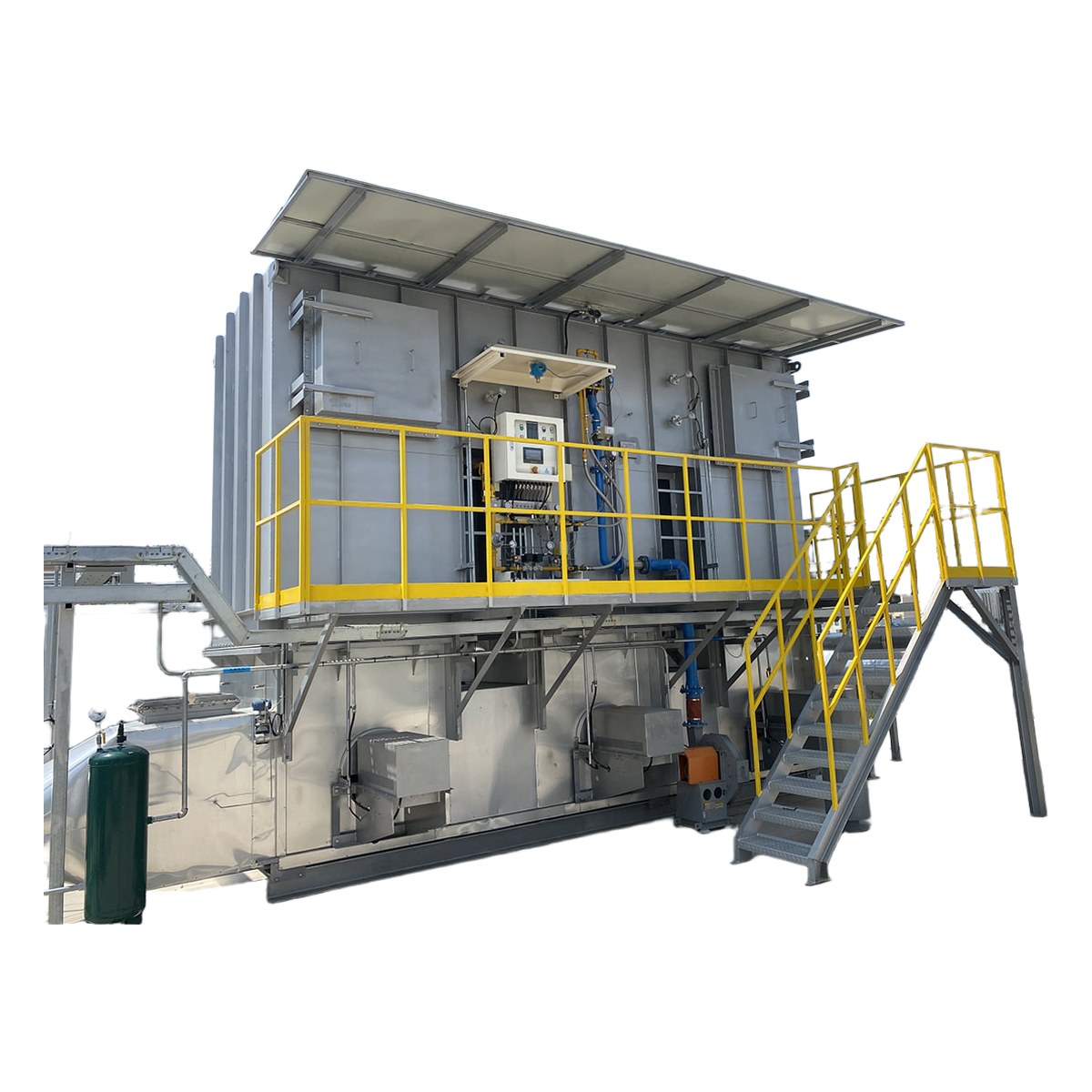
RTO Regenerative Thermal Oxidizer
Professional Process Equipment Supplier
1. Product Overview
The RTO (Regenerative Thermal Oxidizer) is a highly efficient industrial air pollution control device that destroys volatile organic compounds (VOCs) by heating exhaust gases to 800-1000°C, where VOCs undergo thermal oxidation and decompose into harmless carbon dioxide and water. The equipment utilizes ceramic heat exchange media as the thermal storage medium, achieving heat recovery efficiencies of 95% or higher, which significantly reduces fuel consumption during operation. RTO is internationally recognized as one of the most effective technologies for VOCs abatement and is widely applied in chemical, coating, printing, pharmaceutical, electronics, and food industries for organic exhaust gas treatment. It ensures stable compliance with increasingly stringent national and local environmental regulations. Depending on the processing air volume and process requirements, RTO systems are available in three-chamber, rotary, and two-chamber configurations to suit different operating conditions.
2. Working Principle
The working principle of the RTO is based on regenerative heat exchange technology and proceeds through the following steps: First, VOCs-laden exhaust gas is drawn into the regenerative chamber by the induced draft fan, where it is preheated to near combustion temperature as it passes through the high-temperature ceramic heat exchange media. Then, the preheated gas enters the combustion chamber, where it reaches the design temperature of 800-1000°C with the assistance of a burner, and VOCs undergo complete thermal oxidation, decomposing into CO₂ and H₂O. The purified high-temperature gas then passes through another regenerative chamber on the opposite side, transferring its heat to the ceramic media for storage while its own temperature drops significantly before being discharged through the stack. Valve switching or rotary distributors periodically alternate the gas flow direction, enabling the ceramic media to alternately store and release heat for efficient thermal recovery. The three-chamber RTO includes a purge chamber to ensure no untreated gas escapes during switching, achieving destruction efficiencies of 99% or higher. The entire system is automatically controlled by a PLC, providing real-time monitoring and adjustment of temperature, pressure, and flow rate for safe and stable operation.
3. System Classification
3.1 Classification by Structure
| Type | Working Method | Applicable Conditions | Features |
|---|---|---|---|
| Three-Chamber RTO | Three chambers alternate: heat/cool/purge | High concentration, strict requirements | Highest DRE ≥99%, zero bypass leakage |
| Rotary RTO | Rotary distributor continuously switches airflow | Medium-high concentration, large volume | Smooth switching, low pressure fluctuation, compact |
| Two-Chamber RTO | Two chambers alternate: heat/cool | Medium-low concentration, general use | Simple structure, lower investment, DRE ≥97% |
3.2 Classification by Air Volume
| Type | Air Volume Range | Typical Configuration | Application Scenario |
|---|---|---|---|
| Small RTO | ≤10,000Nm³/h | Two/three-chamber design | Labs, small workshop exhaust |
| Medium RTO | 10,000~50,000Nm³/h | Three-chamber/rotary design | Medium plants, coating lines |
| Large RTO | ≥50,000Nm³/h | Rotary/multi-chamber parallel | Large chemical parks, centralized treatment |
4. Detailed Technical Parameters
4.1 Key Component Materials
| Component | Material | Surface Treatment/Spec | Characteristics |
|---|---|---|---|
| Furnace Shell | Carbon steel Q345B | High-temp powder coating | High strength, weather-resistant |
| Combustion Chamber Lining | Refractory castable/ceramic fiber module | Temp rating 1400°C | Insulation, energy-saving |
| Heat Exchange Media | Ceramic saddle/honeycomb packing | Temp rating 1200°C | Heat recovery ≥95%, low pressure drop |
| Ductwork/Stack | SS304/refractory lined | Insulation + galvanized cladding | Corrosion-resistant, low heat loss |
| Valves/Dampers | 316L SS body + high-temp seal | Pneumatic/electric actuator | Fast switching, tight seal |
| Frame/Support | Carbon steel Q235/structural steel | Hot-dip galvanized/powder coated | High load capacity, corrosion-resistant |
4.2 Specification Parameters
| Parameter | Small | Medium | Large |
|---|---|---|---|
| Treatment Air Volume | 3,000~10,000Nm³/h | 10,000~50,000Nm³/h | 50,000~200,000Nm³/h |
| VOCs Concentration Range | 0.5~25%LEL | 0.5~25%LEL | 0.5~25%LEL |
| Design Combustion Temp | 800~1000°C | 800~1000°C | 800~1000°C |
| Heat Recovery Efficiency | ≥95% | ≥95% | ≥95% |
| Destruction Efficiency | ≥99% (3-chamber) | ≥99% (3-ch/rotary) | ≥99% (rotary/multi-ch) |
| Bed Switching Cycle | 60~120 seconds | 60~120 seconds | 60~120 seconds |
| Fuel Type | Natural gas/electric | Natural gas/diesel | Natural gas |
| System Pressure Drop | ≤3,000Pa | ≤3,500Pa | ≤4,000Pa |
| Installed Power | 15~45kW | 45~150kW | 150~500kW |
| Equipment Dimensions (ref.) | 6×3×5m | 10×5×7m | 15×8×10m |
4.3 Performance Indicators
| Indicator | Parameter Value | Test Conditions |
|---|---|---|
| VOCs Destruction Efficiency | ≥99% | Three-chamber RTO, rated airflow |
| Heat Recovery Efficiency | ≥95% | Steady state, ceramic media |
| Outlet VOCs Concentration | ≤20mg/m³ | Inlet ≤2,000mg/m³ |
| NOx Emission | ≤50mg/m³ | Natural gas firing |
| Equipment Leakage Rate | ≤1% | Positive pressure method |
| Operating Noise | ≤85dB(A) | Measured at 1m from equipment |
| Equipment Availability | ≥95% | Annual statistics (including maintenance) |
4.4 Electrical Parameters
| Item | Parameter |
|---|---|
| Power Supply | 3P+N+PE, AC380V±10%, 50Hz |
| Control Power | DC24V (switching power supply) |
| Control System | Siemens S7-1500 PLC |
| HMI | 12-inch color touchscreen |
| Burner Control | Eclipse/Weishaupt auto combustion controller |
| Temperature Detection | Type K/S thermocouples, multi-point monitoring |
| Pressure Detection | Differential pressure transmitters, chamber/duct |
| Safety Interlocks | Over-temp alarm, flame monitoring, gas leak alarm |
| Communication | Ethernet, Modbus TCP, Profinet |
Note: Electrical component brands can be substituted with equivalent alternatives upon request.
5. Core Component Selection
| Component | Recommended Brand | Model | Function |
|---|---|---|---|
| Ceramic Media | Corning/Nuocheng/Domestic | Saddle/Honeycomb ceramic | Heat exchange, recovery ≥95% |
| Burner | Eclipse/Weishaupt | Natural gas/dual-fuel | Auxiliary heating, maintain combustion temp |
| PLC Controller | Siemens S7-1500 | CPU 1515-2PN | System logic control & data management |
| Main Induced Fan | AERZEN/Howden | Centrifugal high-temp fan | Exhaust gas induction & pressure balance |
| Switching Valves | Rotary/diverter valves | Pneumatic/electric butterfly valves | Airflow direction switching, alternation |
| Refractory Lining | RATH/Morgan | Ceramic fiber module | Furnace insulation, reduce heat loss |
| Thermocouple | Omega/Honeywell | Type K/S | Combustion/regenerative chamber temp monitoring |
| Gas Valve Train | DUNGS/Siemens | DMV/SKP series | Gas safety control & regulation |
Note: Core component brands can be configured per customer specification with prior confirmation.
6. Typical Application Fields
Chemical Industry: Treatment of VOCs exhaust containing benzene, toluene, xylene, alcohols, and ketones from chemical production processes. Centralized treatment of reactor vent gas and storage tank breathing losses, meeting chemical park emission standards.
Coating Industry: Treatment of spray booth and curing oven exhaust from automotive, appliance, and metal product painting. After paint-mist pretreatment, the exhaust enters the RTO for efficient, stable destruction.
Printing Industry: VOCs treatment from gravure, offset, and lamination processes using solvent-based inks. Low-concentration, high-volume exhaust is concentrated via zeolite rotor before RTO treatment.
Pharmaceutical Industry: Organic solvent exhaust treatment from API and formulation production, meeting both GMP and environmental requirements.
Electronics Industry: VOCs treatment from semiconductor and PCB manufacturing, requiring high-precision and reliable equipment operation.
7 Design Standards & Certification
7. Design Standards and Certifications
| Standard Category | Standard No. | Standard Name |
|---|---|---|
| International | ISO 9001:2015 | Quality Management System Requirements |
| International | ISO 14001:2015 | Environmental Management System Requirements |
| China | GB 37822-2019 | VOCs Fugitive Emission Control Standard |
| China | GB 31571-2015 | Petrochemical Industry Emission Standard |
| China | GB 31570-2015 | Petroleum Refining Industry Emission Standard |
| China | GB 16297-1996 | Integrated Emission Standard of Air Pollutants |
| EU | IED 2010/75/EU | Industrial Emissions Directive (VOCs limits) |
| EU | EN 15446:2008 | Fugitive VOCs Leak Detection and Repair |
| Industry | CE | EU Machinery Directive 2006/42/EC |
8. Customization Options
| Option | Description | Application Scenario |
|---|---|---|
| Zeolite Rotor + RTO | Low-conc exhaust concentrated via rotor before RTO | High volume, low concentration |
| Waste Heat Recovery Module | Recover RTO outlet heat for process use | Plants with heat energy demand |
| Explosion-Proof Configuration | ExdIIBT4 explosion-proof rating | Chemical/flammable environments |
| Remote Monitoring & Diagnostics | IoT remote O&M platform | Multi-plant/remote management |
| SCR DeNOx Module | Post-RTO SCR for NOx reduction | Areas with strict NOx limits |
| Multi-Fuel Burner | Natural gas/diesel dual-fuel switching | Unreliable gas supply or backup needs |
| CEMS Online Monitoring | VOCs/NOx/CO continuous emission monitoring | Online environmental monitoring requirements |
| Quench Tower + Acid Scrubber | Post-RTO rapid cooling + acid gas removal | Halogen-containing exhaust streams |
9. Warranty Terms
| Warranty Item | Warranty Content |
|---|---|
| Machine Warranty Period | 12 months from acceptance date |
| Core Component Warranty | Burner/PLC/fan: 24 months |
| Wearable Parts Warranty | Ceramic media/valve seals/thermocouples: 12 months |
| Software Upgrade | Free upgrade during warranty period |
| Technical Training | Free training for 2~3 operators during installation |
| After-Sales Response | Phone response within 2 hours, on-site within 24~48 hours |
| Spare Parts Supply | Guaranteed for 5 years after production discontinuation |
Note: Free repair and replacement during warranty for quality-related failures; damage caused by human factors or force majeure is excluded.
10. Packaging & Delivery
| Item | Description |
|---|---|
| Packaging Method | Machine wrapped in moisture-proof film + wooden crate (knock-down) |
| Crate Specification | Export-grade plywood crate (fumigation-free) |
| Moisture Protection | Desiccant + vacuum aluminum foil bag |
| Shock Protection | EPE foam + bubble wrap cushioning |
| Lifting Method | 4-point top lifting |
| Transport Method | Truck/railway/ocean shipping |
Lead time: 60~90 working days after contract signing and deposit received. Installation & commissioning: Seller dispatches technicians for on-site installation, approximately 10~15 working days.
11. Inquiry Information Required
To receive an accurate quotation, please provide the following information:
Exhaust gas treatment volume (Nm³/h)
VOCs species and concentration range (mg/m³)
Exhaust gas temperature and moisture content
Presence of halogens, sulfur, or corrosive components
Existing exhaust system and ductwork conditions
Available fuel type on-site (natural gas/diesel/electric)
Applicable emission standards (national/local/industry)
Whether waste heat recovery function is required
Equipment installation site conditions (area/load-bearing/height)
Power supply and compressed air specifications
Other special customization requirements