Vacuum Feeder
Conveying Equipment
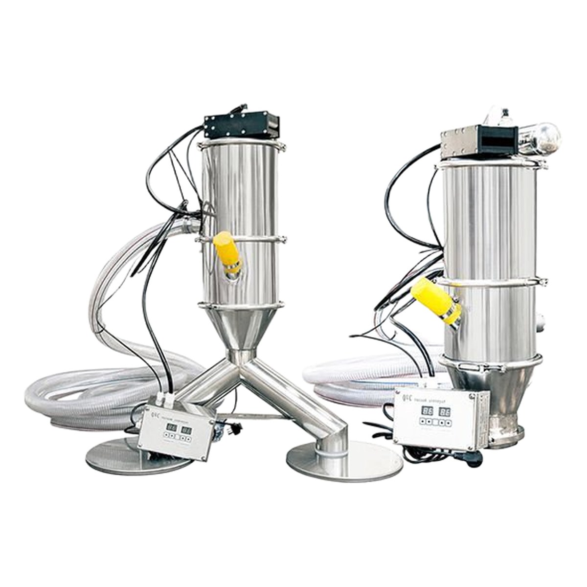
Vacuum Feeder
1. Product Overview
A vacuum feeder is an advanced pneumatic conveying device that utilizes a vacuum pump to generate negative pressure within a closed pipeline system, enabling the dust-free transfer of powdered and granular materials from one location to another. As a key piece of material handling equipment in modern industrial production, the vacuum feeder is engineered to provide reliable, contamination-free, and efficient material transport while maintaining full compliance with Good Manufacturing Practice (GMP) requirements and stringent hygiene standards.
The vacuum feeder operates as a fully enclosed conveying system, ensuring that no dust escapes into the working environment during material transfer. This hermetically sealed operation makes it particularly suitable for applications involving toxic, irritating, or highly potent powders where operator exposure must be minimized. The enclosed design also prevents cross-contamination between different materials, making the vacuum feeder indispensable in multi-product manufacturing facilities.
Primary application sectors include the pharmaceutical industry, where vacuum feeders handle active pharmaceutical ingredients (APIs), excipients, and intermediates with absolute product integrity; the food and beverage industry, where compliance with food safety standards and prevention of foreign material contamination are paramount; and the chemical industry, where corrosive, hygroscopic, and hazardous powders require safe and reliable transfer. Additionally, vacuum feeders are widely employed in the plastics, battery materials, cosmetics, and nutraceutical industries.
The vacuum feeder features a modular design that facilitates rapid disassembly and thorough cleaning, supporting both Clean-In-Place (CIP) and Sterilize-in-Place (SIP) procedures. All product-contact surfaces are manufactured from sanitary-grade materials, typically 316L stainless steel, with interior surface roughness (Ra) values of 0.4 to 0.8 micrometers, ensuring minimal material adhesion and maximum cleanability. The system can be configured for batch or continuous conveying modes, with conveying distances of up to 50 meters horizontally and 10 meters vertically.
2. Working Principle
The fundamental operating principle of a vacuum feeder is based on differential pressure generated by a vacuum source. When the vacuum pump is activated, it evacuates air from the receiving hopper, creating a significant negative pressure (vacuum) zone inside the hopper and the connected conveying pipeline. This pressure differential between the material pickup point (atmospheric pressure) and the receiving hopper (reduced pressure) drives the material-laden air stream through the suction nozzle and into the conveying pipeline.
The material is drawn through the suction nozzle at the feed point and transported along the pipeline into the receiving hopper. Upon entering the hopper, the air velocity decreases significantly, causing the material particles to separate from the airstream under the influence of gravity and inertial forces. The filtration system, positioned at the top of the hopper, provides a secondary and final separation stage by capturing any fine particles that remain entrained in the airstream before the air exits through the vacuum pump. The filter elements are typically constructed from sintered polyethylene (PE), polytetrafluoroethylene (PTFE), or stainless steel mesh, selected based on the particle size and chemical compatibility requirements of the material being conveyed.
A critical feature of the vacuum feeder is the pulse-jet filter cleaning system. As material accumulates on the filter surface during the conveying cycle, the pressure drop across the filter gradually increases. To maintain optimal filtration efficiency and airflow, compressed air pulses are directed through the filter elements in a controlled sequence, dislodging the accumulated material cake and returning it to the hopper. This automatic pulse cleaning ensures consistent conveying performance throughout extended production runs without the need for manual intervention.
Once the hopper has been filled to the predetermined level (detected by level sensors or controlled by a timed cycle), the vacuum pump is deactivated, and the discharge valve at the bottom of the hopper opens to release the material into the downstream equipment or process vessel. The discharge valve may be a butterfly valve, rotary valve, or flap valve, depending on the application requirements. After the discharge cycle is complete, the valve closes and the vacuum cycle begins again, creating a fully automated batch conveying sequence. For continuous conveying applications, dual-hopper systems with alternating fill and discharge cycles are employed, ensuring an uninterrupted material supply to the process.
3. System Classification
3.1 Classification by Vacuum Source
Roots Pump Type: Roots (or rotary lobe) vacuum pumps provide high volumetric flow rates at moderate vacuum levels, making them ideal for conveying large quantities of free-flowing powders and granules over moderate distances. They feature oil-free operation, ensuring zero contamination of the conveyed material, and offer excellent reliability for continuous-duty applications. Roots pump systems are commonly rated for vacuum levels of -40 to -80 kPa and flow rates of 200 to 2000 m³/h. Their robust construction and minimal maintenance requirements make them the preferred choice for high-capacity pharmaceutical and food-grade installations.
Rotary Vane Pump Type: Rotary vane vacuum pumps deliver higher vacuum levels than Roots pumps, typically achieving -80 to -98 kPa, making them suitable for conveying fine, cohesive, or difficult-to-fluidize powders. The higher vacuum capability allows material pickup from deeper containers and over longer conveying distances. However, rotary vane pumps require oil lubrication, necessitating oil separators and filters to prevent oil carryover into the product zone. They are widely used in chemical and industrial applications where high vacuum is essential and where the oil-free requirement can be managed through effective separation systems.
Water Ring Pump Type: Water ring vacuum pumps use a rotating water seal to create vacuum, offering the unique advantage of isothermal compression. The water ring effectively absorbs heat generated during compression, making this type ideal for conveying heat-sensitive materials that could degrade at elevated temperatures. Water ring pumps also tolerate liquid carryover and can handle moist or humid air streams without damage. Typical vacuum levels range from -60 to -90 kPa. They are commonly applied in food processing, chemical handling, and applications involving wet or sticky materials.
Ejector (Venturi) Type: Ejector-type vacuum feeders use compressed air passing through a Venturi nozzle to generate vacuum, eliminating the need for any mechanical vacuum pump. This results in an extremely compact, lightweight, and maintenance-free vacuum source with no moving parts. Ejector systems are ideal for small to medium capacity applications (up to 500 kg/h), short conveying distances, and installations where electrical equipment must be minimized, such as explosion-hazardous environments. The trade-off is higher compressed air consumption, making them less economical for large-scale continuous operations.
3.2 Classification by Conveying Mode
Batch Conveying Mode: In batch mode, the vacuum feeder operates on a cyclic fill-and-discharge sequence. The vacuum pump is activated to draw material into the hopper during the fill phase; once the hopper reaches the target fill level, the vacuum is released and the discharge valve opens to empty the hopper contents. This cycle repeats automatically. Batch conveying is the most common mode for vacuum feeders and is particularly suited for feeding process vessels, mixers, and packaging machines where precise dosing and controlled discharge are required. The fill volume per cycle is precisely controlled by level sensors or timers.
Continuous Conveying Mode: Continuous conveying utilizes dual-hopper or rotary valve discharge systems to provide an uninterrupted material flow. While one hopper is being filled under vacuum, the other is simultaneously discharging material to the downstream process. The alternating cycle ensures that the receiving process never starves for material. Continuous mode is essential for processes requiring constant material supply, such as continuous mixing, extrusion, and tablet compression operations. It achieves effective throughput rates comparable to batch systems while maintaining steady-state material flow.
3.3 Classification by Application Grade
Pharmaceutical Grade: Pharmaceutical-grade vacuum feeders are designed and manufactured to full GMP compliance, with all product-contact surfaces made from 316L stainless steel (or higher alloys) with electropolished finishes (Ra ≤ 0.4 μm). They feature sanitary tri-clamp connections, CIP/SIP capability, FDA-compliant elastomers, and full material traceability with certificates of conformance. Validation documentation (IQ/OQ/PQ protocols) is provided. Design eliminates dead legs, crevices, and other contamination traps, ensuring product purity and facilitating thorough cleaning between product changeovers.
Food Grade: Food-grade vacuum feeders comply with FDA 21 CFR and EU food contact regulations, with product-contact surfaces of 304 or 316L stainless steel and food-grade elastomers. They are designed for easy disassembly and cleaning, with smooth welds and rounded corners to prevent material buildup. While not requiring the same level of documentation as pharmaceutical grade, food-grade units still maintain high hygiene standards and are suitable for handling dry food ingredients, dairy powders, spice blends, nutritional supplements, and similar products.
Industrial Grade: Industrial-grade vacuum feeders are designed for robust performance in demanding manufacturing environments where GMP compliance is not required. They typically use carbon steel or 304 stainless steel construction with standard surface finishes. These units prioritize conveying capacity, durability, and cost-effectiveness over sanitary design features. Common applications include chemical powders, plastic resins, pigments, fillers, building materials, and battery materials where product purity requirements are less stringent but reliability and throughput are critical.
4. Detailed Technical Parameters
4.1 Basic Parameters
| Parameter | Value | Remarks |
|---|---|---|
| Model | ZKF-100 / ZKF-200 / ZKF-300 / ZKF-500 / ZKF-1000 | Capacity-based designation |
| Conveying capacity | 100 - 5000 kg/h | Depends on material and distance |
| Horizontal conveying distance | ≤50 m | Shorter distance yields higher capacity |
| Vertical conveying distance | ≤10 m | Vertical lift reduces capacity significantly |
| Motor power | 0.75 - 11 kW | Selected per model and vacuum source |
| Compressed air supply | 0.4 - 0.6 MPa | For pulse cleaning and ejector type |
| Conveying pipeline diameter | DN40 - DN100 | Selected per capacity and material |
| Hopper volume | 10 - 500 L | Customizable per batch requirement |
| Operating vacuum level | -40 to -98 kPa | Depends on vacuum source type |
| Filter area | 0.5 - 8 m² | Selected per material fineness |
| Control mode | PLC + HMI / Manual | Auto cycle with adjustable parameters |
| Material of construction | SS316L / SS304 / CS | Product contact parts |
4.2 Roots Pump Type Parameters
| Parameter | ZKF-100R | ZKF-200R | ZKF-300R | ZKF-500R | ZKF-1000R |
|---|---|---|---|---|---|
| Conveying capacity (kg/h) | 100-300 | 200-600 | 300-1000 | 500-2000 | 1000-5000 |
| Roots pump power (kW) | 1.5 | 2.2 | 3.0 | 5.5 | 11 |
| Max vacuum level (kPa) | -80 | -80 | -80 | -80 | -80 |
| Pump flow rate (m³/h) | 200 | 350 | 500 | 1000 | 2000 |
| Pipeline diameter | DN40 | DN50 | DN65 | DN80 | DN100 |
| Hopper volume (L) | 10-30 | 20-60 | 30-100 | 60-200 | 150-500 |
| Filter area (m²) | 0.5 | 1.0 | 1.5 | 3.0 | 6.0 |
| Compressed air (MPa) | 0.4-0.6 | 0.4-0.6 | 0.4-0.6 | 0.4-0.6 | 0.4-0.6 |
| Noise level (dB(A)) | ≤75 | ≤78 | ≤78 | ≤80 | ≤82 |
4.3 Ejector Type Parameters
| Parameter | ZKF-100E | ZKF-200E | ZKF-300E | ZKF-500E |
|---|---|---|---|---|
| Conveying capacity (kg/h) | 50-150 | 100-300 | 150-500 | 300-1000 |
| Compressed air consumption (L/min) | 200 | 350 | 500 | 800 |
| Compressed air pressure (MPa) | 0.5-0.6 | 0.5-0.6 | 0.5-0.6 | 0.5-0.6 |
| Max vacuum level (kPa) | -70 | -70 | -65 | -60 |
| Pipeline diameter | DN32 | DN40 | DN50 | DN65 |
| Hopper volume (L) | 5-15 | 10-30 | 20-60 | 40-120 |
| Filter area (m²) | 0.3 | 0.5 | 1.0 | 2.0 |
| No moving parts | Yes | Yes | Yes | Yes |
| Explosion-proof rating | Intrinsically safe | Intrinsically safe | Intrinsically safe | Intrinsically safe |
4.4 Overall Dimensions
| Model | Hopper Dia. (mm) | Hopper Height (mm) | Overall Width (mm) | Overall Height (mm) | Weight (kg) |
|---|---|---|---|---|---|
| ZKF-100 | 250 | 400 | 350 | 900 | 25-40 |
| ZKF-200 | 300 | 500 | 400 | 1050 | 35-55 |
| ZKF-300 | 350 | 600 | 460 | 1200 | 50-80 |
| ZKF-500 | 450 | 800 | 580 | 1500 | 80-130 |
| ZKF-1000 | 600 | 1000 | 750 | 1850 | 130-220 |
4.5 Material Characteristics
| Material Category | Bulk Density (t/m³) | Particle Size | Flowability | Recommended Type |
|---|---|---|---|---|
| Pharmaceutical powders | 0.3-0.8 | 1-200 μm | Poor to moderate | Rotary vane / Roots |
| Food powders (flour, sugar) | 0.4-0.9 | 10-500 μm | Moderate to good | Roots / Water ring |
| Chemical powders | 0.5-1.5 | 5-500 μm | Variable | Roots / Rotary vane |
| Plastic granules/pellets | 0.5-1.0 | 1-5 mm | Good | Ejector / Roots |
| Battery materials (Li-ion) | 0.5-2.0 | 1-50 μm | Poor | Rotary vane |
| Mineral powders | 1.0-2.5 | 1-100 μm | Moderate | Roots / Water ring |
| Pigments and dyes | 0.3-1.2 | 0.1-50 μm | Very poor | Rotary vane |
| Carbon black / silica | 0.1-0.5 | 0.01-0.5 μm | Very poor | Rotary vane (high vac) |
5. Core Component Selection
5.1 Vacuum Pump
The vacuum pump is the heart of the vacuum feeder, determining the system's conveying capacity, vacuum level, and energy consumption. Selection of the appropriate vacuum pump type depends on the material characteristics, required throughput, conveying distance, and operational environment. Roots pumps are the standard choice for most pharmaceutical and food applications due to their oil-free operation, high flow rates, and excellent reliability. They can achieve vacuum levels up to -80 kPa with flow rates from 200 to 2000 m³/h.
Rotary vane pumps are selected when higher vacuum levels are needed, particularly for fine, cohesive, or adhesive powders that resist fluidization. They achieve vacuum levels up to -98 kPa but require effective oil separation systems. Water ring pumps are chosen for heat-sensitive materials and applications involving moist air, as the water seal provides inherent cooling and can tolerate condensate carryover. Ejector (Venturi) pumps are the simplest and most compact option, ideal for small-capacity applications and explosive atmospheres where electrical equipment must be eliminated. Common pump brands include Busch, Becker, Leybold, and Nash, all available with appropriate certifications for the target industry.
5.2 Filtration System
The filtration system is critical for separating conveyed material from the air stream and protecting the vacuum pump from particulate ingress. The filter elements are housed in the upper section of the receiving hopper and serve as the final barrier between the product zone and the vacuum source. Filter media selection is based on particle size, chemical compatibility, temperature resistance, and cleaning requirements. Sintered PE filters offer excellent filtration efficiency (99.9% at 1 μm) and are cost-effective, but are limited to operating temperatures below 80°C. PTFE membrane filters provide superior chemical resistance, temperature tolerance up to 260°C, and excellent release properties for sticky materials.
Stainless steel sintered mesh filters are used in applications requiring CIP/SIP capability, as they can withstand steam sterilization and aggressive cleaning agents. The filter area must be sized appropriately for the conveying air volume and the material's dust loading characteristics; undersized filters lead to excessive pressure drop and reduced conveying capacity, while oversized filters add unnecessary cost and space requirements. The pulse-jet cleaning system uses compressed air at 0.4-0.6 MPa directed through venturi tubes inserted into the top of each filter element, creating a shock wave that dislodges the accumulated dust cake. Pulse duration, interval, and sequence are adjustable via the PLC to optimize cleaning effectiveness for different materials.
5.3 Hopper
The hopper serves as the receiving vessel and temporary storage container for conveyed material. Its design must facilitate complete material discharge without dead zones, bridging, or ratholing. Hopper geometry is typically conical or pyramidal with steep wall angles (minimum 60° from horizontal) to ensure gravity-assisted discharge of even poorly flowing materials. For highly cohesive powders, hopper walls may be polished to Ra ≤ 0.2 μm or coated with anti-stick surfaces such as PTFE to minimize adhesion.
The hopper is equipped with a discharge valve at the bottom, which opens to release material into the downstream process equipment when the vacuum cycle is complete. Discharge valve types include sanitary butterfly valves (most common in pharmaceutical applications), rotary valves (for continuous discharge), and flap valves (for large-capacity applications). Level sensors (capacitive, vibratory, or load cell type) monitor the material level in the hopper and provide feedback to the control system for automatic cycle management. The hopper may also incorporate fluidization pads or vibration aids to promote complete discharge of difficult materials. All hopper connections use sanitary tri-clamp fittings for rapid disassembly and cleaning.
5.4 Control System
The control system manages the entire conveying cycle, including vacuum pump activation, fill time monitoring, filter pulse cleaning, discharge valve operation, and safety interlocks. Modern vacuum feeders employ programmable logic controllers (PLC) with human-machine interface (HMI) touchscreens for parameter setting, real-time monitoring, and alarm management. Key control parameters include vacuum pump run time, fill time, discharge time, pulse cleaning interval and duration, and hopper fill level setpoints.
The HMI provides a visual display of the system status, including current cycle phase, hopper fill level, vacuum level, filter pressure drop, and alarm conditions. Recipe management allows operators to store and recall preset configurations for different materials, enabling rapid product changeover with consistent performance. Communication interfaces (Modbus, Profibus, Ethernet/IP) enable integration with supervisory control and data acquisition (SCADA) systems and distributed control systems (DCS) for plant-wide automation. Safety features include emergency stop, vacuum over-pressure protection, motor overload protection, and filter differential pressure alarms.
5.5 Suction Pipeline
The suction pipeline connects the material pickup point to the receiving hopper and must be designed to minimize pressure drop, material degradation, and product buildup. Pipeline diameter is selected based on the required conveying air velocity (typically 15-25 m/s for dilute-phase vacuum conveying) and the material particle size and density. Pipeline materials include sanitary-grade stainless steel tubing (pharmaceutical and food), aluminum alloy tubing (lightweight industrial applications), and antistatic polyurethane or PTFE-lined flexible hose for connection to mobile containers.
Pipeline fittings must maintain the internal surface finish and minimize turbulence zones where material could accumulate. Sanitary bends with a minimum bend radius of 3D (three times the pipe diameter) are used to reduce particle impact and degradation. The suction nozzle at the feed point is designed to fluidize the material and entrain it into the air stream efficiently; options include simple tube-type nozzles for free-flowing materials, fluidizing nozzles with compressed air assist for cohesive powders, and suction lances for bag and drum emptying. Quick-release couplings and tri-clamp connections facilitate rapid disassembly for cleaning and inspection. Anti-static grounding is mandatory for all pipeline components when handling combustible materials.
6. Typical Application Fields
Pharmaceutical Industry: Vacuum feeders are extensively used for dust-free transfer of active pharmaceutical ingredients (APIs), excipients (such as lactose, microcrystalline cellulose, and magnesium stearate), granules, and tablet press feeds. GMP-compliant designs with 316L stainless steel contact surfaces, electropolished finishes, and CIP/SIP capability ensure product purity and regulatory compliance. Applications include feeding blenders, granulators, fluid bed dryers, tablet presses, capsule fillers, and coating pans. The enclosed transfer eliminates operator exposure to potent compounds and prevents cross-contamination.
Food and Beverage Industry: Vacuum feeders handle a wide range of dry food ingredients including flour, sugar, salt, starch, milk powder, whey protein, cocoa powder, spice blends, and nutritional supplement powders. FDA-compliant materials and food-grade elastomers ensure product safety. The dust-free operation maintains a clean production environment and meets stringent food safety audit requirements. Applications include feeding mixers, sifters, packaging machines, and baking equipment. Easy-clean designs support frequent product changeovers in multi-product facilities.
Chemical Industry: Chemical processing applications involve the transfer of fine chemical powders, pigments, fillers, catalysts, and specialty chemicals. Vacuum feeders handle corrosive, hygroscopic, and hazardous materials safely within enclosed systems. Construction materials are selected for chemical compatibility, with options for Hastelloy, PTFE linings, and special coatings. Applications include feeding reactors, dryers, mills, classifiers, and packaging systems. Explosion-proof designs (ATEX Zone 1/21 or Zone 2/22) are available for flammable dust environments.
Plastics Industry: Vacuum feeders convey plastic resins, pellets, regrind, masterbatches, and additives to injection molding machines, extruders, blow molding machines, and thermoformers. The gentle conveying action minimizes pellet damage and dust generation. High-throughput models with large hopper volumes support continuous production operations. The system can be integrated with material drying hoppers and gravimetric blenders for fully automated material handling. Quick-change pipeline systems enable rapid color and material changes.
Battery Materials Industry: The rapidly growing lithium-ion battery sector requires vacuum feeders for handling cathode materials (lithium cobalt oxide, lithium iron phosphate, NMC), anode materials (graphite, silicon-carbon composites), electrolyte salts, and separator coatings. These materials are often extremely fine (sub-micron), cohesive, and moisture-sensitive, requiring high-vacuum rotary vane systems with moisture-protected construction. Vacuum feeders in this sector must prevent metallic contamination (using non-ferrous construction) and maintain controlled humidity environments. Applications include feeding mixers, coaters, and compaction presses.
7. Design Standards and Certifications
7.1 ISO 9001 Quality Management System
All vacuum feeder products are designed, manufactured, and tested under an ISO 9001:2015 certified quality management system. This ensures consistent product quality, traceability of materials and processes, and continuous improvement of design and manufacturing procedures. Quality documentation includes inspection and test plans (ITPs), material certificates (EN 10204 3.1), and calibration records for all measuring instruments used in production and testing.
7.2 GMP Compliance
Pharmaceutical-grade vacuum feeders are designed and manufactured in full compliance with current Good Manufacturing Practice (GMP) guidelines, including EU GMP Annex 1 and FDA 21 CFR Part 211. Design features include hygienic construction with smooth, crevice-free surfaces; product-contact surfaces of 316L stainless steel with electropolished finishes (Ra ≤ 0.4 μm); sanitary tri-clamp connections; dead-leg-free design; CIP/SIP capability; and complete documentation packages including material certificates, surface finish measurements, and weld records.
7.3 FDA Compliance
Product-contact materials comply with FDA regulations for food and pharmaceutical contact surfaces, including FDA 21 CFR 177.2600 for elastomeric materials and FDA 21 CFR 175.300 for food-contact surface coatings. All product-contact elastomers (gaskets, O-rings, diaphragms) are made from FDA-compliant materials such as EPDM, silicone, or PTFE with appropriate certification. Material certificates of compliance are provided with each unit.
7.4 CE Marking
Vacuum feeders intended for the European market carry the CE marking in accordance with applicable EU Directives, including the Machinery Directive 2006/42/EC, the Low Voltage Directive 2014/35/EU, and the Electromagnetic Compatibility Directive 2014/30/EU. CE-marked units undergo conformity assessment procedures and are supplied with a Declaration of Conformity, technical construction files, and operator manuals in the required European languages.
7.5 ATEX Explosion-Proof Certification
For applications involving combustible dusts or flammable atmospheres, vacuum feeders are available with ATEX certification per Directive 2014/34/EU. ATEX-certified models are designed for use in Zone 1/21 (Category 2G/2D) or Zone 2/22 (Category 3G/3D) hazardous areas. Explosion-proof features include antistatic filter elements, grounded pipeline systems, explosion-proof motors and electrical components, and pressure relief panels. The ATEX certification covers both the equipment category and the specific gas/dust groups for the intended application.
8. Customizable Options
| Configuration Item | Available Options | Application Scenario |
|---|---|---|
| Vacuum source type | Roots pump / Rotary vane / Water ring / Ejector | Selected per material, capacity, and environment |
| Hopper volume | 5 L - 500 L (custom sizes available) | Per batch size and space constraints |
| Filter type | Sintered PE / PTFE membrane / SS sintered mesh / Fabric bag | Per particle size, temperature, and CIP requirement |
| Discharge valve | Butterfly valve / Rotary valve / Flap valve / Slide gate | Per material flowability and discharge rate |
| Material of construction | SS316L / SS304 / Hastelloy / Carbon steel + coating | Per corrosion resistance and industry grade |
| Surface finish | Ra 0.2 / 0.4 / 0.8 μm (electropolished or mechanically polished) | Per GMP class and cleanability requirement |
| Control system | PLC+HMI / Standalone timer / Integration with DCS/SCADA | Per automation level and plant infrastructure |
| Explosion-proof rating | ATEX Zone 2/22 / Zone 1/21 / Non-EX | Per combustible dust classification |
| Suction nozzle type | Standard tube / Fluidizing / Suction lance / Bag dump station | Per material source and pickup method |
| Cleaning system | Manual disassembly / CIP / SIP / WIP (Wash-In-Place) | Per hygiene standard and changeover frequency |
9. Warranty Terms
9.1 Warranty Period
The warranty period for the complete vacuum feeder system is twelve (12) months from the date of commissioning or eighteen (18) months from the date of shipment, whichever occurs first. The warranty period for the vacuum pump unit is twenty-four (24) months from the date of commissioning, reflecting the pump manufacturer's extended warranty policy. The warranty period for consumable components, including filter elements, gaskets, O-rings, and flexible hoses, is six (6) months from the date of commissioning, as these components are subject to normal wear and degradation during operation.
9.2 Warranty Scope
During the warranty period, the supplier shall, at its own expense, repair or replace any component that fails due to defects in design, materials, or workmanship. This includes, but is not limited to, structural failures of the hopper and pipeline system, vacuum pump mechanical failures attributable to manufacturing defects, control system malfunctions due to component failure, and filter element failure due to manufacturing defects (excluding normal clogging from process operation). The supplier shall provide replacement parts within five (5) working days of notification for standard components and within fifteen (15) working days for custom or special-order components.
9.3 Warranty Exclusions
The warranty does not cover damage resulting from improper installation, operation outside the specified design parameters, use of non-approved spare parts or consumables, failure to perform prescribed maintenance, unauthorized modifications or repairs, normal wear and tear on consumable components, or force majeure events. Consequential damages, including production losses and downstream equipment damage, are expressly excluded from the warranty coverage. The warranty is void if the equipment is operated with materials not disclosed at the time of order or in environmental conditions exceeding the specified design limits.
9.4 After-Sales Service
The supplier provides comprehensive after-sales technical support, including remote telephone and email consultation during business hours, with a response time of four (4) hours for critical issues. On-site service is available within forty-eight (48) hours of request for domestic customers and within five (5) working days for international customers. Post-warranty service contracts are available, offering preventive maintenance programs, spare parts packages, and priority response times. Training services, including operation, maintenance, and troubleshooting training, are provided at the time of commissioning and are available on a scheduled basis thereafter.
10. Packaging and Delivery
10.1 Packaging Method
The vacuum feeder system is packaged for safe transportation in modular components, including the hopper assembly, vacuum pump unit, filter assembly, control panel, suction pipeline sections, and accessories. Each component is individually wrapped in moisture-resistant VCI (Volatile Corrosion Inhibitor) film and secured within custom-fitted wooden cases or steel-framed crates. Internal cushioning materials (foam inserts, rubber pads, and corrugated board) protect against shock and vibration during transit. Precision instruments, electrical components, and the control panel are sealed in desiccant-lined polyethylene bags for additional moisture protection.
All packages are clearly marked with the purchase order number, item description, weight, dimensions, and handling instructions. Fragile components bear appropriate warning labels. Export shipments include phytosanitary certificates for wooden packaging materials in compliance with ISPM 15 requirements. Each shipment is accompanied by a detailed packing list identifying all components by part number and quantity.
10.2 Delivery Period
Standard model vacuum feeders (ZKF-100 through ZKF-500 with standard configurations) are delivered within forty-five (45) to sixty (60) working days from the date of confirmed order and receipt of advance payment. Custom-engineered models with non-standard specifications, special materials of construction, or ATEX certification require sixty (60) to ninety (90) working days. Delivery of spare parts and consumable components is within fifteen (15) working days for stock items and thirty (30) working days for made-to-order items. Expedited delivery is available at additional cost, subject to production scheduling confirmation.
10.3 Transportation and Storage
During transportation, packages must be protected from rain, moisture, and direct sunlight. Equipment should be handled with appropriate lifting equipment; do not drop, tip, or stack packages. Upon receipt, inspect all packages for transit damage and report any discrepancies immediately. If the equipment cannot be installed immediately, it should be stored in a dry, covered, well-ventilated area at ambient temperature (5°C to 40°C) with relative humidity below 80%. Do not remove the protective packaging until the equipment is ready for installation. Rotate the vacuum pump shaft by hand every thirty (30) days during extended storage to prevent bearing seizure.
11. Information Required for Inquiry
To ensure accurate equipment selection, optimal configuration, and competitive quotation, please provide the following information when submitting an inquiry for a vacuum feeder system:
| No. | Information Item | Description |
|---|---|---|
| 1 | Material name and properties | Chemical name, bulk density, particle size distribution, moisture content, flowability index, abrasiveness, and any known handling difficulties |
| 2 | Required conveying capacity | Maximum and average throughput in kg/h or t/h, including any anticipated future capacity increases |
| 3 | Conveying distance and elevation | Horizontal distance (m), vertical lift (m), and number of bends in the conveying route |
| 4 | Material source and pickup method | Bag dump, drum, IBC, silo, storage vessel, or other; include container opening dimensions and floor/height constraints |
| 5 | Downstream receiving equipment | Type of equipment being fed (mixer, mill, tablet press, etc.), inlet connection size and type, and any back-pressure considerations |
| 6 | Environmental and safety requirements | ATEX zone classification, GMP class, FDA compliance, containment level (OEB), and any special hygiene or contamination control requirements |
| 7 | Utilities available on-site | Electrical supply (voltage, frequency, phases), compressed air (pressure and flow capacity), and clean utility connections (CIP/SIP) |
| 8 | Installation space constraints | Available floor area, ceiling height, access routes for equipment delivery, and any existing structural or layout limitations |