Pipeline Conveying
Conveying Equipment
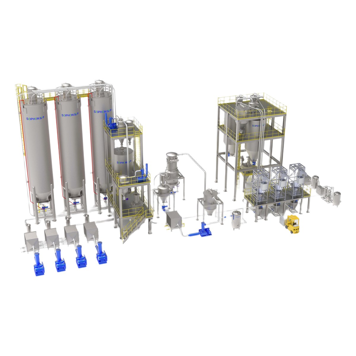
Pipeline Conveying System
EQP-CONV-005 V1.0
Document Classification: Internal Use
1. Product Overview
The Pipeline Conveying System is an advanced enclosed transport solution designed for the continuous or batch transfer of powder and granular bulk materials through fully sealed pipelines. Driven by pneumatic pressure differentials, it moves material efficiently and dust-free between process points, protecting both the product and the working environment from contamination.
The system operates on either positive-pressure (push) or negative-pressure (vacuum) pneumatic conveying principles, moving materials through fully enclosed pipe networks. The fully sealed design ensures zero material leakage, eliminates dust emissions at the workplace, and protects both the product from ambient contamination and the operating environment from particulate pollution.
Pipeline conveying systems are widely adopted in industries where material purity, environmental compliance, and process hygiene are paramount. Typical conveyed materials include chemical powders, pharmaceutical excipients, food-grade granules, cement, fly ash, mineral ores, plastic pellets, and various other bulk solids with particle sizes ranging from fine powders (<10 μm) to coarse granules (up to 50 mm).
Key advantages of the Pipeline Conveying System include: fully enclosed transport preventing material loss and environmental contamination; flexible pipeline routing capable of navigating around obstacles and between buildings; minimal maintenance due to few moving parts within the conveying line; capacity for long-distance transport (horizontal distances up to 500 m and vertical lifts up to 50 m); and seamless integration with silos, hoppers, mixers, and other process equipment.
The system is engineered to comply with international standards for safety, hygiene, and environmental protection. All product-contact surfaces can be fabricated from stainless steel (SS304/SS316L) for sanitary applications, and the system design can meet ATEX explosion-proof requirements for handling combustible dusts. Whether for lean-phase high-velocity transfer or dense-phase low-velocity conveying of fragile materials, the Pipeline Conveying System offers a reliable and customizable solution for modern industrial material handling.
2. Working Principle
2.1 Positive Pressure Conveying
In positive pressure conveying, the air source (typically a roots blower, screw compressor, or centrifugal fan) is installed at the upstream end of the system. The compressed air enters the pipeline and propels the material forward. Material is fed into the pressurized conveying line through a rotary valve, pressure tank, or venturi feeder. The mixture of air and material travels through the pipeline at velocities ranging from 5 m/s to 30 m/s depending on the conveying phase. At the destination, the material is separated from the air stream by a cyclone separator and/or bag filter, and the cleaned air is discharged to atmosphere.
Positive pressure systems are suitable for long-distance conveying (up to 500 m horizontal) and high-capacity applications (up to 100 t/h). Multiple discharge points can be served by diverting valves along the pipeline, making this configuration ideal for distributing material from a single source to several destinations.
2.2 Negative Pressure (Vacuum) Conveying
In negative pressure conveying, the air source is positioned at the downstream end of the system, creating a vacuum that draws material through the pipeline. Material is aspirated from the pickup point through a suction nozzle or feeding hopper. The material-air mixture is conveyed to the receiving vessel where a filter separates the solids from the air stream. The vacuum pump or blower then exhausts the filtered air.
Vacuum conveying is inherently leak-safe: any breach in the pipeline draws air inward rather than leaking material outward. This makes it particularly suitable for handling toxic, hazardous, or highly contaminating materials. It is also the preferred method for multiple-pickup-to-single-destination configurations. However, vacuum systems are typically limited to shorter distances (up to 150 m) and lower capacities compared to positive pressure systems, due to the maximum achievable pressure differential.
2.3 Dense Phase vs. Dilute Phase Conveying
Dilute phase conveying operates at high air velocities (15–30 m/s) with low material-to-air ratios (typically 1:10 to 1:30 by mass). Particles are fully suspended in the air stream and travel at nearly the same velocity as the conveying air. This mode is suitable for non-friable, non-abrasive materials and offers high throughput with relatively simple equipment. However, the high velocity can cause particle degradation and pipeline wear.
Dense phase conveying operates at low air velocities (2–10 m/s) with high material-to-air ratios (typically 10:1 to 50:1 by mass). Material moves in slugs, plugs, or moving-bed patterns rather than as individual suspended particles. This gentle conveying mode minimizes particle breakage, reduces pipeline wear, and consumes less conveying air per unit of material transported. Dense phase systems typically require higher operating pressures (0.1–0.4 MPa) and are ideal for fragile, abrasive, or cohesive materials such as pharmaceutical powders, sugar, carbon black, and cement.
2.4 Rotary Valve Feeding
The rotary valve (also known as a rotary airlock or rotary feeder) is the most common feeding device in positive pressure dilute phase systems. It consists of a rotating shaft with multiple vanes that create airlock pockets, allowing continuous material feed from an atmospheric hopper into a pressurized conveying line while minimizing air leakage. Rotary valves are available in various configurations including standard drop-through, side-entry, and blow-through designs, with rotor clearances engineered for the specific material and pressure differential.
2.5 Cyclone and Bag Filter Separation
At the receiving end of the conveying system, the material must be separated from the air stream. Cyclone separators use centrifugal force to remove larger particles (>10 μm) from the gas stream with efficiencies of 85–95%. For finer particles or higher collection efficiency requirements, bag filter (fabric filter) units provide >99.9% collection efficiency down to sub-micron particle sizes. In many systems, a cyclone is used as a primary separator followed by a bag filter as a secondary (polishing) stage to achieve both high recovery and compliance with particulate emission regulations.
3. System Classification
3.1 Classification by Conveying Principle
Pipeline conveying systems are primarily classified by the pressure regime and conveying phase employed. Each configuration offers distinct advantages for specific application requirements:
| Type | Principle | Pressure Range | Velocity | Typical Application |
|---|---|---|---|---|
| Positive Dilute Phase | High-velocity suspension flow | 0.01–0.1 MPa | 15–30 m/s | Non-friable powders, granules, plastic pellets |
| Positive Dense Phase | Low-velocity slug/plug flow | 0.1–0.4 MPa | 2–10 m/s | Fragile materials, abrasive powders, cement |
| Negative Dilute Phase | Vacuum suction suspension | -0.01 to -0.06 MPa | 15–25 m/s | Short-distance, multi-point pickup, hazardous materials |
| Combined (Push-Pull) | Vacuum pickup + positive push | Vacuum + positive | Variable | Long distance with multiple pickup points |
3.2 Classification by Pipeline Diameter
The pipeline diameter is selected based on the required conveying capacity, material particle size, and conveying distance. Standard nominal diameters range from DN50 to DN300:
| Pipe Diameter (DN) | Inner Diameter (mm) | Typical Capacity Range | Common Application |
|---|---|---|---|
| DN50 | 50 | 0.5–2 t/h | Small-scale, lab/pilot systems |
| DN65 | 65 | 1–5 t/h | Pharmaceutical, fine chemicals |
| DN80 | 80 | 2–10 t/h | Food ingredients, additives |
| DN100 | 100 | 5–20 t/h | General chemical, mineral powders |
| DN125 | 125 | 10–35 t/h | Medium-capacity industrial conveying |
| DN150 | 150 | 15–50 t/h | High-capacity, building materials |
| DN200 | 200 | 30–75 t/h | Bulk cement, fly ash, alumina |
| DN250 | 250 | 50–90 t/h | Large-scale mining, power plants |
| DN300 | 300 | 70–100 t/h | Major bulk terminal operations |
3.3 Classification by Application Industry
Pipeline conveying systems are further categorized by the industry sector they serve, each with unique requirements for hygiene, safety, and material compatibility:
| Industry | Key Requirements | Common Materials | Typical Configuration |
|---|---|---|---|
| Chemical | Corrosion resistance, ATEX compliance | Resins, pigments, catalysts, soda ash | Positive dense phase, SS316L pipes |
| Pharmaceutical | FDA/cGMP compliance, containment | APIs, excipients, granules | Negative dilute phase, sanitary design |
| Food & Beverage | Hygienic design, CIP capability | Flour, sugar, salt, milk powder | Positive/negative dilute, food-grade SS304 |
| Power Generation | High capacity, abrasion resistance | Fly ash, coal powder, limestone | Positive dense phase, wear-resistant pipes |
| Building Materials | High throughput, cost efficiency | Cement, sand, gypsum, fly ash | Positive dense phase, carbon steel pipes |
4. Detailed Technical Parameters
4.1 Basic Parameters
The following table summarizes the fundamental technical specifications applicable to the Pipeline Conveying System product line. Values shown represent standard ranges; specific project configurations may vary based on material properties and process requirements.
| Parameter | Specification | Unit | Remarks |
|---|---|---|---|
| Horizontal Conveying Distance | ≤500 | m | Longer distances available on request |
| Vertical Conveying Distance | ≤50 | m | Includes elevation changes in pipeline |
| Conveying Capacity | 0.5–100 | t/h | Depends on material and pipe diameter |
| Pipeline Diameter | DN50–DN300 | mm | Selected per capacity and material |
| Operating Pressure | -0.09 ~ +0.4 | MPa | Negative (vacuum) to positive pressure |
| Conveying Air Velocity | 2–30 | m/s | Dense phase: 2–10; Dilute phase: 15–30 |
| Material-to-Air Ratio | 1:30 to 50:1 | kg/kg | Dilute: low ratio; Dense: high ratio |
| Operating Temperature | -20 to +200 | °C | Extended range with special materials |
| Number of Pickup Points | 1–6 | pcs | Expandable with manifold design |
| Number of Discharge Points | 1–8 | pcs | Using diverter valves |
| Power Supply | 380/400/415/440 | V, 50/60 Hz, 3-phase | Other voltages available |
| Control Mode | PLC + HMI / DCS | — | Remote monitoring optional |
4.2 Positive Dilute Phase Parameters
Positive dilute phase systems are the most common configuration for general-purpose conveying of non-friable materials. The following parameters apply to standard positive pressure dilute phase systems:
| Parameter | Specification | Unit |
|---|---|---|
| Conveying Pressure | 0.01–0.10 | MPa (g) |
| Conveying Velocity | 15–30 | m/s |
| Material-to-Air Ratio | 1:10 to 1:30 | kg material / kg air |
| Maximum Distance | 500 (horizontal) | m |
| Maximum Lift | 50 (vertical) | m |
| Capacity Range | 0.5–60 | t/h |
| Pipe Diameter Range | DN50–DN200 | mm |
| Air Source Type | Roots blower / Centrifugal fan | — |
| Air Source Pressure | 0.05–0.15 | MPa (g) |
| Feeding Device | Rotary valve / Venturi feeder | — |
| Separation Device | Cyclone + Bag filter | — |
| Typical Power Consumption | 0.01–0.05 | kWh/t·m |
4.3 Dense Phase Parameters
Dense phase systems are designed for gentle conveying of fragile, abrasive, or cohesive materials. They operate at lower velocities with higher material concentrations, resulting in reduced product degradation and pipeline wear.
| Parameter | Specification | Unit |
|---|---|---|
| Conveying Pressure | 0.10–0.40 | MPa (g) |
| Conveying Velocity | 2–10 | m/s |
| Material-to-Air Ratio | 10:1 to 50:1 | kg material / kg air |
| Maximum Distance | 500 (horizontal) | m |
| Maximum Lift | 50 (vertical) | m |
| Capacity Range | 1–100 | t/h |
| Pipe Diameter Range | DN80–DN300 | mm |
| Air Source Type | Screw compressor / Piston compressor | — |
| Air Source Pressure | 0.20–0.80 | MPa (g) |
| Feeding Device | Pressure vessel / Dome valve | — |
| Separation Device | Bag filter / Receiver tank | — |
| Typical Power Consumption | 0.005–0.03 | kWh/t·m |
| Pipeline Wear | Low (10–50% of dilute phase) | — |
| Product Degradation | Minimal (<1% fines generation typical) | — |
4.4 Dimensional Parameters
System dimensions vary significantly based on capacity, pipeline routing, and the number of pickup/discharge points. The following table provides typical dimensions for standard configurations:
| Component | Dimension (L×W×H) | Unit | Weight Range |
|---|---|---|---|
| Pressure Vessel (Small, 0.5 m³) | 1,200×800×1,800 | mm | 300–500 kg |
| Pressure Vessel (Medium, 2.0 m³) | 2,000×1,200×3,000 | mm | 800–1,500 kg |
| Pressure Vessel (Large, 5.0 m³) | 2,800×1,800×4,200 | mm | 2,000–4,000 kg |
| Roots Blower Skid (Small) | 1,500×800×1,200 | mm | 400–800 kg |
| Roots Blower Skid (Large) | 2,500×1,200×1,800 | mm | 1,200–2,500 kg |
| Cyclone Separator | 800×800×2,500 | mm | 200–600 kg |
| Bag Filter Unit | 1,200×1,000×3,500 | mm | 500–1,500 kg |
| Rotary Valve (DN150) | 400×400×500 | mm | 50–80 kg |
| Control Panel | 800×600×1,800 | mm | 80–150 kg |
4.5 Material Characteristics Parameters
The performance of a pneumatic conveying system is highly dependent on the physical properties of the material being conveyed. The following table outlines the key material parameters that must be considered during system design and selection:
| Parameter | Typical Range | Unit | Design Impact |
|---|---|---|---|
| Bulk Density | 50–3,000 | kg/m³ | Determines pipe size and air volume |
| Particle Size (d50) | 1–50,000 | μm | Affects conveying mode and velocity |
| Moisture Content | ≤5 | % | High moisture causes plugging |
| Angle of Repose | 25–45 | ° | Affects hopper and feeder design |
| Friability Index | 1–10 | Scale | Determines need for dense phase |
| Abrasiveness | Low / Medium / High | — | Determines pipe material and wear provisions |
| Temperature Sensitivity | -20 to +200 | °C | Affects pipe and gasket materials |
| Explosibility (Kst) | 0–500 | bar·m/s | Determines ATEX and safety requirements |
| Cohesiveness | Free-flowing to Very cohesive | — | Affects feeder and pipeline design |
| Toxicity | Non-toxic to Highly toxic | — | Determines containment and filter requirements |
5. Core Component Selection
5.1 Air Source Equipment
The air source is the heart of the pneumatic conveying system, providing the pressure differential or vacuum necessary to move material through the pipeline. Selection depends on the required conveying pressure, air volume, and system configuration:
- Roots Blower: The most commonly used air source for dilute phase systems. Provides pressures up to 0.15 MPa (g) for positive pressure or -0.06 MPa for vacuum service. Available in sizes from 2.2 kW to 250 kW. Offers oil-free conveying air, low maintenance, and reliable performance. Typically used with rotary valve feeding systems.
- Screw Compressor: The primary air source for dense phase conveying systems. Provides pressures from 0.2 MPa to 0.8 MPa (g). Oil-free screw compressors are preferred for food and pharmaceutical applications. Available from 7.5 kW to 500 kW. Delivers consistent, pulsation-free air flow suitable for plug conveying.
- Centrifugal Fan: Suitable for low-pressure, high-volume applications such as short-distance vacuum conveying. Provides pressures up to 0.02 MPa. Low energy consumption but limited in conveying distance and capacity. Best for light, free-flowing materials.
- Piston Compressor: Used for very high-pressure dense phase applications (>0.4 MPa). Provides the highest pressures among standard air sources. Higher maintenance requirements but essential for extreme long-distance or high-capacity conveying.
5.2 Feeding Device
The feeding device introduces material into the conveying pipeline in a controlled manner while maintaining the pressure boundary between atmospheric and conveying conditions:
- Rotary Valve (Airlock): The most versatile feeding device for dilute phase systems. Available in drop-through, side-entry, and blow-through configurations. Rotor designs include open, closed, and shrouded types. Standard sizes from DN100 to DN400. Material construction: cast iron, SS304, SS316L, or wear-resistant alloys. Critical design parameters include rotor clearance, leakage rate, and fill efficiency.
- Blow Tank (Pressure Vessel): Used in dense phase systems as the primary feeding device. Available in volumetric capacities from 0.1 m³ to 10 m³. Operates on a batch filling and pressurized discharge cycle. Equipped with dome valves or butterfly valves for reliable sealing under pressure. Suitable for abrasive, fragile, and high-temperature materials.
- Venturi Feeder: A simple, no-moving-parts feeder that uses the venturi effect to entrain material into the conveying air stream. Suitable only for low-capacity, short-distance applications. No air leakage issues but limited to free-flowing materials.
- Screw Feeder: Provides precise, continuous metering of material into the conveying line. Often combined with a rotary valve for positive pressure applications. Suitable for cohesive or bridging-prone materials.
5.3 Conveying Pipeline
The conveying pipeline forms the transport path for material movement and must be carefully designed for durability, flow efficiency, and minimal pressure drop:
- Pipe Material: Carbon steel (Q235/20#) for general industrial applications; SS304 for food and standard chemical applications; SS316L for pharmaceutical and corrosive chemical applications; Wear-resistant steel (NM400/CrMo alloy) for abrasive materials such as sand, cement, and mineral ores; Aluminum alloy for lightweight installations; HDPE/PP for corrosive chemical environments at low pressures.
- Pipe Construction: Seamless pipes for pressures above 0.2 MPa; ERW (Electric Resistance Welded) pipes for standard dilute phase; Flanged connections for DN100 and above; Quick-connect couplings (Bauer type) for DN50–DN80; Elbows with wear-back or ceramic lining at high-wear locations; Minimum bend radius of 3× pipe diameter (5× for abrasive materials).
- Pipeline Accessories: Diverter valves (2-way to 8-way) for routing material to multiple destinations; Sight glasses for visual flow monitoring; Sampling ports for material quality checks; Pressure relief valves for safety; Expansion joints for thermal movement accommodation; Drain ports for cleaning and maintenance.
5.4 Separation and Dedusting Equipment
At the receiving end of the conveying system, efficient separation of material from the air stream is essential for product recovery and environmental compliance:
- Cyclone Separator: A centrifugal separation device that removes >90% of particles larger than 10 μm. No moving parts, low maintenance, and low pressure drop. Available in single and multi-cyclone configurations. Typically used as a primary separator followed by a bag filter for final cleaning. Constructed in carbon steel, SS304, or SS316L.
- Bag Filter (Pulse-Jet): A fabric filter unit providing >99.9% collection efficiency down to sub-micron particle sizes. Uses pulse-jet cleaning for continuous operation. Filter media selection includes polyester, PTFE membrane, Nomex, and anti-static variants. Filter area ranges from 10 m² to 500 m² depending on air volume. Equipped with differential pressure monitoring for filter condition indication.
- Receiver Tank (Silo): A vessel for temporary storage of conveyed material after separation. Equipped with level indicators, vent filters, and discharge devices. Available in volumetric capacities from 0.5 m³ to 100 m³. Design per ASME or GB 150 pressure vessel standards where applicable.
5.5 Control System
Modern pipeline conveying systems incorporate advanced control systems for automated, reliable, and safe operation:
- PLC (Programmable Logic Controller): Siemens S7-1200/1500 or Allen-Bradley CompactLogix series. Provides sequential control of conveying cycles, monitoring of process parameters (pressure, temperature, level), and alarm management. Supports Profibus/Profinet, EtherNet/IP, and Modbus TCP communication protocols.
- HMI (Human-Machine Interface): Touchscreen panel (7–15 inch) for local operation and monitoring. Displays real-time system status, trending of key parameters, and historical alarm logs. Supports recipe management for multiple material types and conveying modes.
- DCS Integration: For plant-wide control system integration. Provides OPC-UA or OPC-DA interfaces for data exchange with higher-level SCADA/DCS systems. Supports remote start/stop, parameter adjustment, and performance monitoring from the central control room.
- Safety Instrumented System (SIS): For applications involving hazardous or explosive materials. Provides emergency shutdown, over-pressure protection, and ATEX-compliant interlock functions. Designed per IEC 61511 functional safety standards.
6. Typical Application Fields
6.1 Chemical Industry
In the chemical industry, pipeline conveying systems are extensively used for the transfer of raw materials, intermediates, and finished products between reactors, dryers, mills, silos, and packaging lines. Materials commonly conveyed include PVC resin powder, titanium dioxide, carbon black, soda ash, catalyst powders, pigments, and various polymer pellets. Systems in this sector typically require corrosion-resistant construction (SS316L or lined pipes), ATEX explosion-proof compliance for combustible dusts, and sealed design to prevent release of toxic or odorous materials.
6.2 Pharmaceutical Industry
Pharmaceutical manufacturing demands the highest standards of product purity, containment, and regulatory compliance. Pipeline conveying systems in this sector handle active pharmaceutical ingredients (APIs), excipients (lactose, microcrystalline cellulose, starch), granules, and tablet press feed materials. Key requirements include FDA/cGMP-compliant design with sanitary finishes (Ra ≤0.8 μm), containment performance (OEB Level 3–5) for potent compounds, CIP/SIP capability, and full validation documentation (IQ/OQ/PQ). Vacuum conveying is predominant in pharma due to its leak-safe nature and ease of cleaning.
6.3 Food and Beverage Industry
Food-grade conveying systems handle a wide variety of materials including wheat flour, sugar, salt, milk powder, cocoa powder, coffee beans, rice, and spice powders. Hygiene is paramount: all product-contact surfaces must be fabricated from food-grade SS304 or SS316L with smooth finishes. Designs must accommodate CIP (Clean-In-Place) requirements, prevent cross-contamination between product runs, and comply with FDA 21 CFR and EU 1935/2004 food contact regulations. Systems are often configured for easy disassembly and inspection.
6.4 Power Generation
In coal-fired and biomass power plants, pipeline conveying systems are critical for handling fly ash, bottom ash, coal powder, and limestone for flue gas desulfurization. These high-capacity systems (up to 100 t/h) typically employ dense phase conveying to minimize pipeline wear from abrasive ash particles. Wear-resistant pipe materials (basalt-lined, ceramic-lined, or chromium carbide overlay) are standard. Systems must operate reliably under continuous duty conditions and interface with ash silos, conditioning equipment, and bulk truck loading facilities.
6.5 Building Materials Industry
The building materials sector is one of the largest users of pneumatic conveying systems, particularly for cement, fly ash, gypsum, limestone powder, and sand. Cement plants employ dense phase conveying for transporting finished cement from mills to silos and from silos to packing machines. These high-throughput systems (50–100 t/h) operate continuously and must withstand highly abrasive materials. Carbon steel pipes with wear-resistant bends are standard, and dust emission compliance is a key environmental requirement.
7. Design Standards and Certifications
All Pipeline Conveying Systems are designed, manufactured, and tested in accordance with relevant international and national standards. The following certifications and standards compliance are maintained across our product range:
| Standard / Certification | Scope | Applicability | Certifying Body |
|---|---|---|---|
| ISO 9001:2015 | Quality Management System | All manufacturing and service processes | Third-party certification body |
| CE Marking (2006/42/EC) | Machinery Safety Directive | All equipment placed on EU market | Notified Body |
| ATEX 2014/34/EU (Zone 20/21/22) | Equipment for explosive atmospheres | Systems handling combustible dusts | Third-party certification body |
| FDA 21 CFR Part 177 | Food contact material compliance | Food and pharmaceutical systems | FDA (self-declaration + audit) |
| GB/T 19001-2016 | Chinese QMS standard (equiv. ISO 9001) | Domestic market compliance | CQC / CAS |
| ASME Section VIII Div. 1 | Pressure vessel design and fabrication | All pressure vessels >0.1 MPa | ASME Authorized Inspector |
| GB 150-2011 | Chinese pressure vessel standard | Domestic pressure vessels | SEI (Special Equipment Inspection) |
| IEC 61511 / ISA 84 | Safety Instrumented Systems | SIS for hazardous material handling | Third-party certification body |
| NFPA 652 / 654 | Combustible dust hazard analysis | Systems handling combustible dusts | Qualified fire protection engineer |
| GMP / cGMP | Good Manufacturing Practice compliance | Pharmaceutical conveying systems | Regulatory authority inspection |
Documentation provided with each system includes: certificate of conformity, material test reports (per EN 10204 3.1), pressure vessel certification (where applicable), ATEX certificates for explosion-proof components, factory acceptance test (FAT) reports, and comprehensive operation and maintenance manuals. Third-party inspection by an independent inspection agency can be arranged upon request.
8. Customizable Options
Pipeline Conveying Systems are highly configurable to meet specific project requirements. The following table outlines the key customization options available:
| No. | Option | Standard Configuration | Customization Available | Lead Time Impact |
|---|---|---|---|---|
| 1 | Pipe Material | Carbon steel (Q235) | SS304, SS316L, wear-resistant steel, HDPE, ceramic-lined | +1–4 weeks |
| 2 | Air Source | Roots blower | Screw compressor, piston compressor, centrifugal fan | +1–2 weeks |
| 3 | Feeding Device | Rotary valve (standard) | Pressure vessel, venturi feeder, screw feeder, vacuum pickup nozzle | +1–3 weeks |
| 4 | Separation Equipment | Cyclone + bag filter | Multi-cyclone, HEPA filter, wet scrubber, bin vent | +1–2 weeks |
| 5 | Control System | PLC + HMI (Siemens) | DCS integration, remote I/O, IoT/cloud monitoring, SCADA | +2–4 weeks |
| 6 | ATEX Certification | Non-ATEX standard | ATEX Zone 20/21/22, Ex-proof motors, intrinsically safe instruments | +3–6 weeks |
| 7 | Sanitary Design | Industrial grade finish | FDA/cGMP sanitary, Ra≤0.8μm, CIP/SIP, tri-clamp connections | +2–4 weeks |
| 8 | Pipeline Routing | Standard straight + elbows | Custom 3D routing, expansion joints, flexible hose sections | +1–2 weeks |
| 9 | Insulation & Tracing | No insulation | Mineral wool insulation, electric heat tracing, steam tracing | +2–3 weeks |
| 10 | Noise Attenuation | Standard enclosure | Sound attenuated blower enclosure (≤75 dB(A) at 1 m), silencers | +1–2 weeks |
9. Warranty Terms
The following warranty terms apply to all Pipeline Conveying Systems supplied by our company. Warranty coverage begins from the date of commissioning or 90 days after delivery, whichever occurs first.
| Warranty Category | Coverage Period | Scope of Coverage | Exclusions |
|---|---|---|---|
| Standard Warranty | 12 months | Manufacturing defects in materials and workmanship for all system components including air source, feeding device, pipeline, separation equipment, and control system | Normal wear parts (filter bags, seals, gaskets), damage from misuse or improper maintenance |
| Extended Warranty | 24 months | Extended coverage for pressure vessels, pipelines, and structural components; includes annual inspection and preventive maintenance service | Consumable items, damage from process upsets, force majeure events |
| Wear Parts Warranty | 6 months | Rotary valve rotors and housings, pipeline bends, filter bags and cartridges, sealing elements | Normal abrasive wear exceeding design expectations, unauthorized material substitutions |
Warranty claims must be submitted in writing within the warranty period, accompanied by detailed descriptions of the defect, photographs, and operational data. Our technical team will evaluate each claim within 48 hours and provide repair, replacement, or remediation as appropriate. On-site warranty service is available globally with response times of 24–72 hours depending on location.
Post-warranty service agreements and spare parts packages are available to ensure continued reliable operation throughout the system lifecycle. We maintain a dedicated spare parts inventory for all standard components with delivery within 5–15 business days.
10. Packaging and Delivery
All Pipeline Conveying System components are packaged and shipped in accordance with international standards for industrial equipment transport. Packaging methods are selected based on component size, weight, fragility, and destination requirements.
10.1 Packaging Standards
- Small Components: Rotary valves, instrumentation, control panels, and accessories are packed in reinforced corrugated cartons with foam cushioning and moisture barrier bags. Desiccant packs are included for ocean shipments.
- Medium Components: Cyclones, bag filter housings, and receiver tanks are secured on wooden pallets with steel banding and covered with VCI (Vapor Corrosion Inhibitor) wrapping for corrosion protection during transit and storage.
- Large Components: Pressure vessels, blower skids, and large silos are loaded onto flat racks or open-top containers with custom wooden crating and heavy-duty strapping. Lifting lugs are clearly marked for safe handling.
- Pipeline Sections: Pipes are bundled and secured with steel straps on wooden bearers. Flanged ends are protected with wooden or plastic flange covers. Special care is taken to prevent denting or deformation during transport.
10.2 Delivery Terms
Standard delivery terms are FCA (Incoterms 2020) from our manufacturing facility. CIF, DAP, and DDP terms are available upon request. Typical delivery schedules are as follows:
| System Size | Engineering & Design | Manufacturing | FAT & Packing | Total Lead Time |
|---|---|---|---|---|
| Small (DN50–DN80) | 1–2 weeks | 4–6 weeks | 1 week | 6–9 weeks |
| Medium (DN100–DN150) | 2–3 weeks | 6–8 weeks | 1–2 weeks | 9–13 weeks |
| Large (DN200–DN300) | 3–4 weeks | 8–12 weeks | 2 weeks | 13–18 weeks |
Expedited delivery schedules are available for urgent projects with a surcharge of 15–25% depending on the required compression of lead time. Partial shipments can be arranged to allow early commencement of installation activities.
11. Information Required for Inquiry
To ensure accurate system design and quotation, the following information should be provided when submitting an inquiry. Incomplete information may result in delays or assumptions that could affect system performance.
| No. | Information Item | Description / Required Details | Importance |
|---|---|---|---|
| 1 | Material Properties | Material name, bulk density (kg/m³), particle size distribution (d10/d50/d90), moisture content, angle of repose, friability, abrasiveness, explosibility (Kst value), toxicity classification | Critical |
| 2 | Conveying Distance | Total horizontal distance (m), total vertical lift (m), number and angles of bends (30°/45°/60°/90°), pipeline routing sketch if available | Critical |
| 3 | Conveying Capacity | Required throughput (t/h), operating mode (continuous or batch), batch size and cycle time if applicable, peak vs. average capacity requirements | Critical |
| 4 | Conveying Mode Preference | Dilute phase or dense phase, positive pressure or vacuum, or open to recommendation based on material properties | High |
| 5 | Number of Pickup/Discharge Points | Quantity and locations of material pickup points, quantity and locations of discharge points, sequence of operations (simultaneous or sequential) | High |
| 6 | Site Conditions | Available space dimensions, ambient temperature range, altitude, electrical supply (V/Hz/ph), compressed air availability, existing equipment interfaces | High |
| 7 | Regulatory Requirements | ATEX zone classification, FDA/cGMP compliance, pressure vessel code (ASME/GB/EN), local environmental emission limits, other regulatory requirements | Medium |
| 8 | Project Schedule | Target delivery date, installation and commissioning timeline, factory acceptance test (FAT) requirements, training requirements for operating personnel | Medium |
Please provide as much of the above information as possible when submitting your inquiry. Our engineering team will review the data and may request additional details to finalize the system design. A detailed technical proposal including P&ID, layout drawings, and commercial terms will be provided within 5–10 business days of receiving a complete inquiry package.